This thread has been locked.

If you have a related question, please click the "Ask a related question" button in the top right corner. The newly created question will be automatically linked to this question.

MPY634: correlated and uncorrelated noise

Part Number: MPY634

Hello Guys,

Good day.

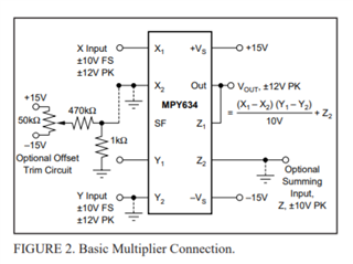
If using the MPY634 and tying both inputs to the same input signal...Vx = Vy = Vin, then should we expect Vout to be Vin^2 ?  Will we see a reduction in noise at the output?  will we see greater SNR at the output then as compared to the input SNR?

Our customer just wanted to understand the notion of correlated and uncorrelated noise and how it plays.

Thanks and regards,

Art

  • Hi Art,

    Assuming that the MPY634 is connected as a basic multiplier as seen in datasheet Fig. 2, the transfer function equation is as seen in left side of the figure:

    Assuming If VX1 = VY1 and  VX2 = VY2 = VZ2 = 0 V, then ideally VOUT will be equal to Vin^2 . However, the equation is ideal and there will be voltage offset, small input bias current differences between inputs, and internal/external noises that will combine to move VOUT away from the ideal level.

    Each current and voltage noise source within the MPY634 has its own independent noise characteristics. These noises generated internal to the MPY634 will be uncorrelated. The noises can be treated as small errors added to the voltages applied to and associated with VX1, VY1, etc. Referred to their inputs they will receive the same multiplication effect provided by the transfer equation. Since noise is produced within the MPY634 internal input circuits the differences in the between them will be affected by the multiplication factor in accordance with the transfer equation.

    If for example the VX1 and VY1 noise sources produced a peak of the same level at the same instance (correlated), then the change in the ideal VOUT level would be the equivalent of the Vin^2 you mentioned. However, since the noise will be uncorrelated the output change will be a function of the VX1 and VY1 levels at that particular moment in time. Because noise is added by the multiplier stages the SNR will be degraded at the VOUT compared to the SNR presented at the multiplier inputs by the preceding circuits.

    Regards, Thomas

    Precision Amplifiers Applications Engineering

  • Hello Thomas,

    Thanks for the reply. This is how the customer understand the multiplier operation. But he still have a follow-up question in the form of an example. Below are his response in verbatim.

    "Input to both multiplier inputs has a signal of 0.5 Vpeak, also noise at input measures 0.05 Vpeak. Apparent SNRp = 0.5/0.05 = 10. At output of multiplier Vs^2/Vn^2 = 0.5^2/0.05^2 = 100. Is this an increase in SNR?
    But if input signal was 0.1 and noise is 0.05 then SNR = 2. a multiplier output: 0.1^2/0.05^2 = 4. it seems there is an apparent SNR increase at multiplier output with input increasing signal to noise ratio, but not so much if input signal to noise ratio is low to start with. Am I seeing this correctly?"

    Thanks and regards,

    Art

  • Hello Art,

    I am not sure you can separate the signal and noise in that manner. Each input to the multiplier is the sum of the intended signal and its associated noise at any instance in time. The unique noise at each input modulates the signal applied at each input. Therefore, the multiplier output voltage is the product of the signal+noise amplitude at the Y input, times the signal+noise amplitude at the X input.

    Certainly there will be the input SNR established at each input by the amplitude of the applied signal in relation to the noise of each input. However, the resulting output SNR must be determined by the output signal in relation to the output noise.

    Regards, Thomas

    Precision Amplifiers Applications Engineering

  • Hi Art,

    when taking the square of the momentary value of an input signal, the square will be higher than the input signal, if the input signal is >1V, but it will be smaller than the input signal, if the input signal is <1V.

    The noise superimposed to the input signal will also be treated differently depending on whether the momentary value of input signal is >1V or <1V. As consequence the noise amplitude becomes modulated by the momentary value of input signal.

    So, what's going on in detail here not only depends on the amplitude of input signal but also on the shape of input signal and on the amplitude and shape of the noise signal as well.

    In the following simulation the input signal is squared by the help of a discrete analog multiplier. The input signal consists of a 0.1Hz sine of 1V amplitude superimposed by white noise with 1mV amplitude.

    See the pictures and the simulation file here:

    https://e2e.ti.com/support/amplifiers/f/amplifiers-forum/993580/mpy634-belongs-to-this-thread

    Please note how the noise at the output of squarer "VF4" depends on the momentary value of "VG2" and is modulated by it.

    So, I think there's no simple answer. And it's questionable what SNR shall mean here. I don't think that it can mean the same for the input signal as for the output signal as the input signal has entirely lost its shape after passing the squarer.

    Kai

  • Kai,

    Thank you much for your detailed analysis, explanation and noise model. 

    Regards, Thomas

    Precision Amplifiers Applications Engineering

  • Thanks Guys!

    I will let you know in case customer have further inquiries but I might direct the customer to this thread  to explain his use-case better.

    Best regards,

    Art

  • Hi Art,

    The extent of the information we have for the MPY634 is the datasheet datasheet. The analog multipliers are legacy products designed during the Burr-Brown days several decades ago. Details about the noise characteristics and behaviors are overall nonexistent. If the customer does have more questions about the MPY634 we will do our best to support them with the very limited information we have.

    Regards, Thomas

    Precision Amplifiers Applications Engineering