This thread has been locked.

If you have a related question, please click the "Ask a related question" button in the top right corner. The newly created question will be automatically linked to this question.

AMC1311-Q1: AMC1311-Q1 & AMC3302

Part Number: AMC1311-Q1
Other Parts Discussed in Thread: AMC3302, AMC1311, TLV6001

Hello Smith,

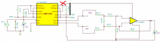
I have simulated both the isolated voltage sensing & Isolated current sensing using AMC1311 & AMC3302 respectively. I have added both files. 

Kindly, check & confirm whether to proceed further.

I am using MCP39F511A whose input ADC range is +/- 600mV .

I have simulated isolated voltage sensing file PSPICE for TI & isolated current measurement in TiNA

Isolated Voltage Sensing.DSN 

sbam444_Isolated Current Sensing.TSC

  • Hi Biswajit,

    I would just like to confirm with you that you are not seeing problems with your simulations or calculations, you are simply asking for a check? 

    Please confirm that you are using the MCP +/-600mV input for both devices? 

    Your feedback (5k x 2) and gain (3k) resistors for the AMC1311 circuit match nicely to +/-600mV, (2V output * 3/10), but I see that you have unity gain configuration for the AMC3302 circuit. Do you plan on not using the full input range of the AMC3302? 

    Can you share the 130uohm shunt resistor part number and desired current magnitudes (nominal, maximum) to be measured? 

    I am not positive that powering the TLV6001 from LDOout of the AMC3302 is ok. I think it will be, but I will confirm this connection with the design team. 

    When you go to layout, please be sure to connect the DCDC_HGND and HGND with a short, low impedance trace. I am happy to review layout if you would like another check when you are ready before manufacturing. 

  • Hi Biswajit,

    I spoke with the designer and the TLV6001 positive supply should not be connected to LDOout. This pin's voltage can vary between 2.4V and 3.2V and should not be connected to anything externally.  

  • Hii Alexander,

    Yes I am not facing any problem in simulation. But you can check once.

    Yes I am using MCP39F511A  ADC range( +/-600mV/GAIN )for both devices. Actually MCP does have  selectable gains for both current & voltage which can be varied from 1 to 32. 

    I can go for higher value of the shunt(200 or 300 microohms) to utilize the  higher range of AMC3302 . We have to take a call during the testing based on the heat generation. Current range is from 2 A to 100 A. Maximum current can be  105A at maximum. Below are the tentative shunt values

    1) MPN:- WSLP3921L3000FEA, Manufacture :- Vishay Dale

    2) MPN:- PU3921FKNP90U2L, manufacturer :- Yageo

    My question is whether we will be able to achieve 0,1 % error in voltage & current measurement. My worry mainly is in current measurement. Should i use 0.1% shunt ???

    Yes we will review the layout once we complete the PCB

  • Hi Biswajit,

    Both shunt's you've selected look good on paper. As you said it will depend on the heat generation, primarily the construction of the PCB. Larger and thicker copper planes will dissipate more heat. Extra layers with thermal relief vias, heatsinks, fans, etc will help too. 

    Do you anticipate continuous current at 105A or would that be a short duration case?

    Unfortunately I doubt you will be able to find a 0.1% shunt at this low resistance level. 0.1% variation at 200uohm is +/-2uohm which would be very difficult to manufacture (or even measure)! Additionally, at resistances this low, solder resistance and PCB assembly can play a large role in equivalent sensing resistance. You may need to perform a gain and offset calibration at production in order to reliably achieve 0.1%. 

    What is your ambient temperature range? 

  • Hii Alexander,

    No actually our continuous current will be 100A . I have taken a 5% margin.

    To your second question depending on the battery voltage of charging EV, current will be controlled. Ours is a 200-1000V charger so till 300V, current will be 100A after that current will reduce as the charger is power limited.

  • Hi Biswajit,

    I see. These shunts should be ok but careful PCB design should be considered. You may want to use a heavier copper weight (2oz, 3oz, 4oz) and thermal management vias to additional layers in order to help dissipate the heat. As I said before I am happy to look at the layout when you are ready. Please let me know if you have additional questions.