This thread has been locked.

If you have a related question, please click the "Ask a related question" button in the top right corner. The newly created question will be automatically linked to this question.

LPV521: Unpowered OpAmp Input Impedance with Small Input Voltages

Part Number: LPV521

Hi,

We are facing a similar issue to the one mentioned in the related question (https://e2e.ti.com/support/amplifiers-group/amplifiers/f/amplifiers-forum/234909/maintain-input-impedance-when-amplified-is-not-powered), but with a twist: our input voltage source (which should see a very high impedance) has only very small voltages (below 200mV).

So far, this is our approximate circuit:

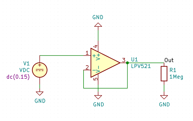
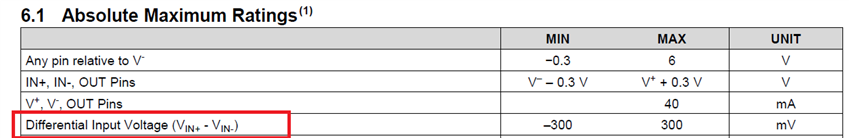
This leads to our first question: How much input leakage can we expect for a unpowered LPV521 with input voltages smaller than 200mV? Theoretically, the ESD diodes should not be forward biased at that point...

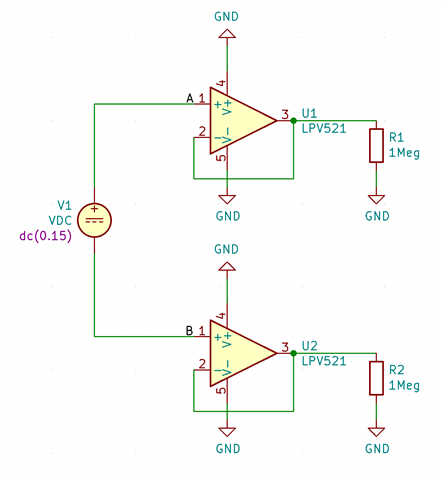
The other question is: We see a rather large bias current if the voltage is applied differentially across two LPV521:

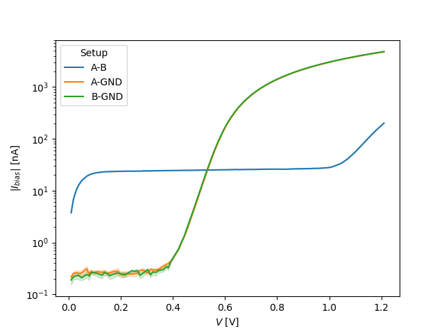
We went ahead and measured the input impedance, and got the following input bias current:

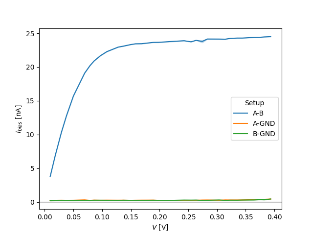
A-B is differential, A-GND is the test voltage applied only to the upper OpAmp and B-GND is the test voltage applied only to the lower OpAmp (plus/minus some offset error, since we're operating our ampere-meter on the edge of it's accuracy).

As you can see, the differentially applied voltage results in a much high input bias current. Is this a known phenomenon? Theoretically, we would have guessed that they should look similar (except that we would see a breakdown at twice the ESD forward voltage, which we do), but there is an additional 24nA of bias current which we can not explain...

We used both a shorted and non-shorted opamp supply rail for the measurement, with negligible differences.

Thanks for any insight!

Cheers, Dominik

  • Hello Dominik,

    The A-B measurement should not be more current than A-GND or B-GND.

    The current should be the sum of thermal junction leakage current and diode current. At room temperature, thermal leakage will be very low. Diode current should increase by 10X for every 60mV applied. 

    In summary, the measured A-GND and B-GND may be correct, A-B is likely not correct.
    Can A-B be remeasured again? Can A-GND and B-GND curves be plotted with Y axis logarithmic?

  • Hi Ron,

    Thanks for the quick response!

    The current should be the sum of thermal junction leakage current and diode current. At room temperature, thermal leakage will be very low. Diode current should increase by 10X for every 60mV applied. 

    As far as I know this holds for forward-biased diodes, reverse biased ones have essentially a constant $I_s$.
    But if I read this correctly, the bias current of an unpowered LPV521 should not be excessively higher than a powered LPV521, given that the ESD diodes are not forward biased too much?

    In summary, the measured A-GND and B-GND may be correct, A-B is likely not correct.
    Can A-B be remeasured again?

    We thought as much, and already measured it multiple times, with varying configurations - to no avail. Most measurements yielded the curve seen in the Figure above. We did get the same curve as "A-GND" or "B-GND" by connecting B to ground and measuring "A-B" (which may sound obvious, but unpowered circuits seem to be a tricky business...)

    Can A-GND and B-GND curves be plotted with Y axis logarithmic?

    Sure. Note that the current for V<0.4 is likely lower than the accuracy of our ampmeter, so I'd say this essentially reads as "below 300pA".

    Also note that, as expected, the diode forward voltage in "A-B" is reached at approximately twice the voltage as with "A-GND" or "B-GND" (which is expected because the voltage applied has to forward-bias two ESD diodes...)

  • Dominik,

    The A-B is current due to the diff input diode pair. This path bypasses V+ and V-

  • Hi Ron,

    I was not aware of these diodes, thanks for pointing them out!

    During the investigation of these differential input diodes, we have figured out the root cause of the issue: 50Hz noise. It was strong enough to result in a forward-biasing of the ESD-diodes. Due to the non-linear character of circuits containing diodes, source-superposition does no longer hold which resulted in a non-zero current flowing. We did not observe this in A-GND and B-GND since then GND also saw the same 50Hz noise, effectively preventing forward-biasing.

    We resolved this by exploiting a capacitor already in place from B to a previously floating node, adding a resistance to ground, essentially creating a tank-circuit which seems to be sufficiently low impedance for 50Hz s.t. the diodes no longer become forward-biased.

    Best,

    Dominik