This thread has been locked.

If you have a related question, please click the "Ask a related question" button in the top right corner. The newly created question will be automatically linked to this question.

TLV9351: Problem with output signal failure during Bulk Current Injection (BCI) test

Part Number: TLV9351
Other Parts Discussed in Thread: TLV9354

Hi everyone,

The circuit I have built is a very simple amplifier. I am having problems during the BCI test (60mA). Although the input signal is stable, I see peak signals at the output.

I verify that the input signal is not changing. The problem is affected by the amplifier.

I tested for situations where C2 is used and not used, the result has not changed.

TLV9351 Out

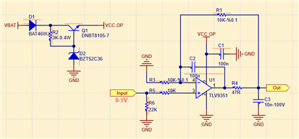
How can I solve this problem?

BR,

Onur.

  • Hi Onur,

    The TLV9354 has internal EMI filters to help reject any signals outside the bandwidth of the device which should help during EMI testing. You could also try adding some filtering at the input of the op amp (assuming this is where the BCI signals are injected) to increase the EMI filtering roll off.

    I would recommend increasing R4 to ~500ohms, C2 to 20nF, and R1 and R3 to 50k. These component values are calculated based on the procedure for the designing the Riso with Dual Feedback circuit in our TI Precision Lab Videos on Stability.

    Lastly, the EMI performance can depend heavily on PCB layout. All traces should be as short as possible and there should be a solid ground plane to provide all return currents (especially EMI signals) a low impedance return path. 

    Thank you,

    Tim Claycomb

  • Hi Tim ,

    Thanks for your quick reply.

    I used 2 and 4 layer pcbs while doing the tests. In some previous works, we have some experience in layout. In this case, I will apply your suggestions first.

    R4 ---- 560R

    C2 ---- 10nF

    R1 & R3 ---- 100K

    Is it okay to change the values in this way? I want to use the existing ones without adding a new component.

    Thank you,

    BR,

    Onur.

  • Hi Onur,

    Yes, those component values should be ok.

    Thank you,

    Tim Claycomb

  • Hi Tim,

    Unfortunately, there has not been a change. I perform the test in the range of 1-400MHz (ISO11452-4 BCI).

    I tested both with the values from you and the values I said. Transient still occurs in the output signal or sometimes the output signal drops to zero.

    What is your suggestion?

    Br

  • Hi Onur,

    where is the EMI coupled in? Input or output?

    Kai

  • Hi Onur,

    During the BCI test, does 60mA flow through the net labeled "input"? I am only vaguely familiar with the BCI testing. 

    As mentioned previously EMI testing results can greatly depend on PCB layout. Do you have a unbroken solid GND plane on your PCB?

    Thank you,

    Tim Claycomb

  • Hi Kai,

    This is a sensor circuit. Sensor feeds are Vbat and gnd.

    First stage, only the vbat and gnd cables run through the current probe. I am not putting a current into the output signal yet. Normally, when there is no opamp, the opamp input signal (sensor out) does not change even in 200mA test. So the opamp input signal is OK. Gnd plane is solid. 

    BR

  • Then I would add a low pass filter to the input of OPAmp.

    Kai

  • Hi Tim,

    GND plane is solid. As I told Kai, I give the sensor output as the input to the opamp. I inject current only to the sensor supply ie VBat and GND wires. The sensor does not change the output signal even in more challenging conditions. This means that there is no distortion in the input of the opamp signal.

    By the way, the sensor and opamp are not discrete systems. They create blocks of the same circuit and have the same gnd plane.

  • Hi Onur,

    I agree with Kai, a low pass filter on the input should help. 

    Also, this current will need to flow somewhere and should not flow into the input of the op amp. If it is flowing through R6 and is centered about 0V this may cause the op amp to rail to one or the other supplies. Are you able to measure the voltage at R6 with a scope during your testing? However, an RC filter should remove a lot of the injected signal so this may not be a major concern.

    Thanks,

    Tim Claycomb

  • Hi Tim,

    Unfortunately the low pass filter did not work. I used 100K + 10nF .

    What is your another suggestion?

    BR

  • Hi Onur,

    can you post a complete schematic showing the sensor section as well?

    What sensor do you use? What is VBAT?

    Kai

  • Hi Onur,

    Are you biasing the input voltage up during your testing? I would not expect good results if the input of the amplifier is at 0V causing the output to drive into GND.

    Lastly, are you able to measure the voltage at R6 during your testing?

    Thank you,

    Tim Claycomb