This thread has been locked.

If you have a related question, please click the "Ask a related question" button in the top right corner. The newly created question will be automatically linked to this question.

INA168: Feedback mode is not understood for Current-Sense Amplifier

Part Number: INA168
Other Parts Discussed in Thread: INA180,

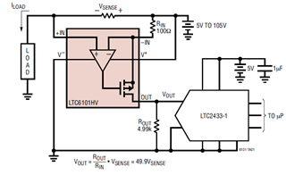
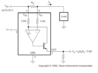
For datasheet of IN168, The feedback is positive feedback. in this mode, we can not use formula of V+=V-.

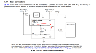
But for datasheet of INA180, it is also a Current-Sense Amplifier ,The feedback is negative feedback, These two structures are obviously not the same. How do you understand that

  • Hello User,

    This system has two feedback systems.  The transistor has feedback as well to the system.  So if the current on the transistor increases because the output of the amplifier increases the current on the transistor increases but this will then drop the voltage of Vin+ of the amplifier as there will be a larger voltage drop across the input 5k resistor.  This creates the negative feedback needed for the circuit to function.

    The INA180 is a different architecture and does not have the additional feedback component and has a voltage output as the INA168 is current out.

    Hope this answer your question let me know. If this helped.  You could also simulate this in a simulator with an ideal amplifier to get a better understanding.

  • Yes, this is also a negative feedback, the op amp is reversing the phase by 180 degrees

    but i read the datasheet of LTC6101, It's the same architecture, but it feeds back to V-

    Of course, this is another IC that you may not be familiar with

    Now I'm selecting the IC for schematic design,

    The way of two chips are connected makes me a little confused.

  • oh sorry, i understood suddenly, the LTC6101 is use PMOS, so it must be feed back to V-, 

    Only then can it be negative feedback

  • Hello,

    I assume this covers your question.  If not please repost a questions or add further to this post.