This thread has been locked.

If you have a related question, please click the "Ask a related question" button in the top right corner. The newly created question will be automatically linked to this question.

LM311-N: oscillating in zero crossing detector circuit

Part Number: LM311-N
Other Parts Discussed in Thread: LM393-N, LM311, TL331, LM339, LM393

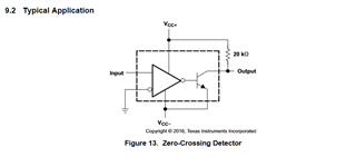
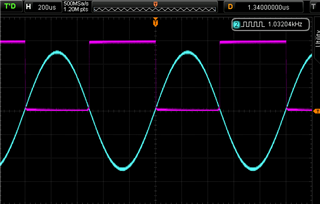
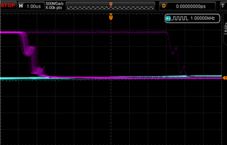
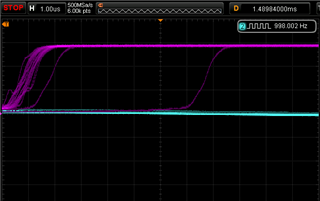
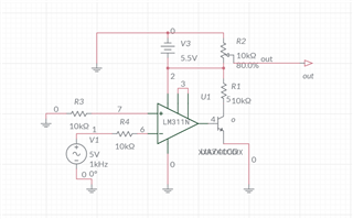
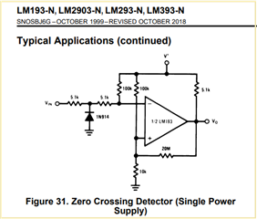
I'm using the LM311N/LM211P in a basic zero crossing detector circuit as in Fig 13. below with a pull-up voltage divider to give 3.3V logic output.  The attached scope pictures (1V per division) show the oscillations on  both edges at frequencies between 1kHz-3kHz. The output is more stable at higher frequencies above 6kHz.

The input is coming from a function generator, 1kHz  5V PP sine wave.  comparator supply:  single  +5.5V - 0.

I tried some of the suggestions on page 12 of the datasheet "CIRCUIT TECHNIQUES FOR AVOIDING OSCILLATIONS IN COMPARATOR APPLICATIONS" but has not resolved the issue.

Tried a separate power supply for the output, it didn't make any difference.

am I missing something here, is it  possible to get a stable output in the 1kHz-3kHz range  without using a dozen resistors/capacitors for such a basic task?

is there any modern easier to use comparators better suited for this type of application that you can recommend?

Thanks.

  • Hi Adam,

    just add hysteresis Relaxed

    Another nice option is figure 31 of datasheet of LM393-N. It also includes hysteresis.

    Kai

  • Hi Kai,

    tried it, makes the edges smoother but the jitter won't go away.

  • Hi Adam,

    can you post your schematic?

    Kai

  • Adam

    As Kai suggested, please share your schematic and please indicate what alternatives you have tried.  Hysteresis is the most common solution for such a problem, so please indicate how much hysteresis you were able to add.  Please also note that the LM311 is a fairly fast, higher voltage comparator.  Are you powering with split supplies and then ground referencing the output.  That is a unique capability of the LM311, but if you do not require that feature, switching to a lower speed device such as the TL331 would be a good alternative.  We will wait to review your schematic before providing any additional comments.

    Chuck

  • The schematic below is the baseline as it stands at the moment after removing all the changes I made.

    25k-30k hysteresis made a noticeable difference, at least it removed the knees from the edges.

    everything is powered from a single supply.

    The LM311 was not selected for any particular reason other than it was in the first cabinet I opened.

    .

  • Adam,

    Not sure what you are doing here on the output...no wonder you are getting funny results.

    You do not need an external transistor, the transistor shown in the typical application is internal to the LM311. Ground pin 1 and tie the pull-up resistor to the collector output (pin 7), and pin 7 becomes the output.

    Please note that the LM311 is NOT a ground sensing input, so the input range is limited to +0.3V to +3.8V on a single +5V supply. Grounding the input violates the lower input range and this can also cause "funny" behavior.

    See if you can look in the cabinet for a TL331, LM393 or LM339...these have ground sensing inputs.

    Also beware that it looks like you are placing a bipolar input signal on the input. The input cannot go below ground, so if the signal generator is putting out +2.5 to -2.5V, the -2.5V is violating the -0.3V limit AND is causing the input to clamp to GND - which can also cause funny behavior.

  • I'm not using an external transistor, the drawing software doesn't have a template for the LM311,  it is there to refer to the internal transistor.

    will look into the points you made above as well as the alternatives.

    Thanks.

  • Hi Adam,

    but even then your schematic makes no sense, as you haven't connected the output line to the output of LM311. Please don't feel offended, but your schematic is pure nonsense Scream

    As already suggested I would do it this way:

    Kai

  • I should've explained it's the output to the microcontroller which is disconnected, you can remove R2 and probe the LM311 output pin directly it won't make any difference.

    I'm going to implement the "zero crossing detection" using the microcontroller internal comparator for simplicity and fewer external parts.

    I may revisit this in the future to get to the bottom of it.

    Thanks to everyone for your input and swift response.

    you can close the case for now.

  • understood Adam

    thanks for following up and if you need any additional support, feel free to repost.

    Chuck