This thread has been locked.

If you have a related question, please click the "Ask a related question" button in the top right corner. The newly created question will be automatically linked to this question.

OPA211: Unit Gain Bandwidth

Part Number: OPA211
Other Parts Discussed in Thread: OPA192, TPS7A84A, LMH6629

Hi


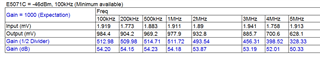
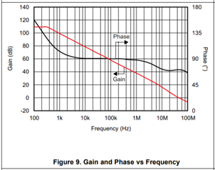
Gain Bandwidth Product = 45MHz (G =1)

After briefly examining, the gain bandwidth product is not under expectation

Please refer to the attached ppt for more details

(1) Check sinusoidal is straightforward. How you identify this specification?

(2) For realizing effective bandwidth limitation, whether it makes any sense to connect the signal through from input to output directly without any components mounted?

(3) Is the conclusion in the attached ppt correct?


Do you have any comment / recommendation to clearly analysis?

OPA211 typical unit gain bandwidth 20210422.pptx

Thanks

Regards

Ben


  • Hi Ben,

    the OPA211 is not suited for 100R loads. The OPA211 is a 600R OPAmp.

    Kai

  • HI Ben,

    Kai has a good point about the 100 Ohm output load. It is a good arrangement from a transmission line termination standpoint, but too low of load resistance for the OPA211 to drive. The datasheet indicates a 10 kilohm load, but it seems the complex load impedance including capacitance could distort the true response at tens of Megahertz.

    The OPA211 was introduced about 15 years ago and finding information about the original characterization is becoming less easy to find. Despite this, I am attempting to see if I can find how the gain-bandwidth measurement was accomplished. If we can find that information that would aid in making a correct measurement.

    Regards, Thomas

    Precision Amplifiers Applications Engineering

  • Hello Ben,

    I received information from our Characterization Engineer. Loading the OPA211 output with 100 ohms reduces the open-loop gain (AOL) and the bandwidth as a result. AOL across frequency is obtained by measuring the changes in the op amp output voltage and input voltage offset  across the frequency range used to establish the AOL curve. The op amp output and input voltage offset node employ high-speed buffers to drive an analyzer's inputs for the measurements.

    So it does look like the OPA192 is driving a 10 kilohm load, but a high-speed buffer drives the cable and analyzer's 50 Ohm input.

    Regards, Thomas

    Precision Amplifiers Applications Engineering

  • Hi Thomas


    Thanks for the investigation and description!

    I simply removed the load and drive only the analyzer input

    which is 1M ohm, the typical bandwidth is probably feasible with 10x probe to capture the waveforms but coaxial cable connected. Please refer to the attached ppt for more details


    OPA211 typical unit gain bandwidth 20210428.pptx

    Actually I intended to build a post amplifier capable of identifying the output rejection as PSRR etc. 

    LDO: TPS7A84A_TI 


    Figure 7 and Figure 8 PSRR VS. Frequency

    If the amplifier gain is flat over frequency of interest, the curve could be obtained by simple conversion

    Target :


    Gain: 60 dB ~ 100dB

    Frequency band: 10Hz ~ 10MHz

    Resolution of Oscilloscope: 1mV / Div


    To preserve the signal integrity, driving 100 ohm may be essential.

    Could you please recommend the amplifier of the best suit to the intended establish?


    Thanks

    Regards

  • Hey Ben, on your original question see attached. There is very little in the measured data in the OPA211 to go on, but the updated 2019 model seems to be acting as expected. 

    Some OPA211 model testing for Aol to closed loop mapping.docx

    On your actual requirement of measuring a small PSRR signal through 10Mhz with 60dB gain? that is a required gain bandwidth product of 1000X10Mhz or 10GHz - really? If so, you will need multiple stages and start with the LMH6629. 

  • Hi Michael


    Thanks for the information in the article!

    I simply built a multiple stages with about 60dB gain

    The gain flatness is effective about 5MHz


    Although OPA211 is not suited to drive the 100 ohm load,

    Is it still suitable to what I am intending to do according to the table above?

    May I make a brief evaluation to the output rejection as PSRR before LMH6629 available ?


    I am going to follow your recommendation, implement another one with LMH6629 to the best suited


    Regards

    Ben

  • Hi Ben,

    The OPA211 is a very high performance precision operational amplifier, but at 5 MHz it has little open-loop gain (Aol) remaining as can be seen in datasheet Fig. 9 below. The graph show it only has about 20 dB (10 V/V) of Aol at 5 MHz. When applied in your -10 V/V per stage application results in a large gain error. Additionally, the CMRR and PSRR have fallen off a great deal at 5 MHz, as seen in the datasheet Figure 6 and 7.

    I agree with Michael that the LMH6629 is better fit for your 5 MHz application than the OPA211. Primarily because it is designed and spec'd for RF applications, which 5 MHz falls under. And it is specified to drive a 100 Ohm load directly. You can likely achieve satisfactory 60 dB gain at 5 MHz performance, with two LMH6629 op amp stages instead of three. Do be careful about the capacitive load on the output. The "Typical Performance Characteristics" curves indicate that with just a matter of picofarads it requires a series output isolation resistor (Riso) be added. That could be an issue. 

    The LMH6629 falls in TI's High-Speed Amplifiers product line, which is a different product line the Precision Amplifiers which are supported on this e2e forum. If you address your application inquiry to them directly, they may have additional high-speed op amps they can recommend that will suite your application well.

    Regards, Thomas

    Precision Amplifiers Applications Engineering