This thread has been locked.

If you have a related question, please click the "Ask a related question" button in the top right corner. The newly created question will be automatically linked to this question.

LMH5401EVM: Operating Frequency range

Part Number: LMH5401EVM
Other Parts Discussed in Thread: LMH5401, ASH, , THS4551

The data sheet says this EVM has an upper frequency limit of 5 GHz. The amp itself has an upper frequency range of 6 GHz. What makes the EVM good to a lower frequency limit? Is it the layou, the material used for the board construction, the use of coax connectors or something else?

The reason I ask is that we are struggling with getting the desired (and specified) performance out of an LMH5401 amp in one of our designs and the cause of the limitation  on the EVM might help us understand why our design isn't performing as we think it should.

  • Hi Ash,

    I think the best idea is that you post a schematic and tell something about your application Relaxed

    Kai

  • Kai,

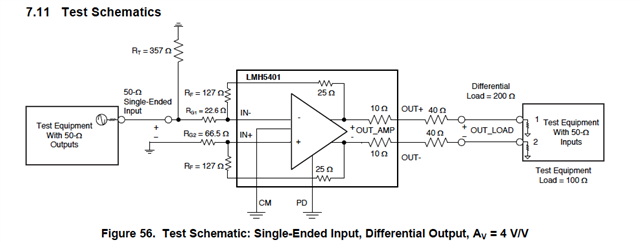
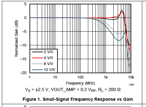
    Look at Figure 56 in the LMH5401 (attached for your reference). I can't even replicate what the data sheet says should be the small signal response (As per figure 1) using this exact schematic and the TI LMH5401EVM Eval Board

    Ash

  • Hi Ash,

    Several factors can negatively effect the bandwidth. You must properly configure the differential load impedance of your test equipment, ensure cables are not unnecessarily long and are 50 Ohm matched, ensure proper grounding, and cover the unused input on the EVM with a 50 Ohm matched termination. Can you post the measurement plots you are getting and a picture of your setup?  It may be something simple that is causing an additional capacitive load or unintentional attenuation.

    Best,

    Sam

  • Sam,

    Thought of that. We tried this with a variety of different cables and properly calibrated equipment using both SAs and network analyzers. The results are consistent and not up to spec. And the results are the same for the TI eval board and a board of our own design. Different boards, different cables, different test equipment, changed one thing at a time, all lead to the same results. There's something else going on here.

    I don't mean to sound like a know it all, but I've been doing this sort of thing for over 30 years. The issue really isn't in the measurement. It's something else. There is some fundamental issue that we're missing. I'm not sure what it is. What I would really love to have someone tell me is that they have in fact been able to replicate the performance TI claims they get using that eval board.

    And the performance of that eval board raises a question in its own right. The amp data sheet says the amp is good to 6 GHz. The data sheet says that performance was verified using the LMH5401EVM eval board. The LMH5401EVM eval board data sheet says it's only good to 5 GHz! So how the heck did TI come up with the plots they present in their amp data sheet?

    I am starting to wonder if we're on a snipe hunt here.

    Ash

  • Hey Ash, one side note is that the datasheet plots were done with a 4port network analyzer -those use an autocal box to take the cable out where the unused input port was likely just terminated in 50ohm for the network analyze. . It would also help to show your measure plot vs the PDS one. In doing a datasheet, the team is striving to show the best possible result, 

  • Michael,

    We tried this thing with both 2 and 4 port network analyzers. We just can't seem to get the results you folks get. 

    I understand that the data sheets show the best case scenario, but what we are seeing is a fairly substantial drop in signal strength at the higher end of the frequency range using the EVM

    Frequency MHz 1000 1500 2000 2500 3000 3500 4000 4500 5000 5500 6000
    Gain Setting 2V/V output dBm -101.282 -101.044 -101.215 -98.507 -97.373 -96.53 -95.313 -104.507 -106.157 -106.788 -109.195

    In the vein of the data sheet showing the best case scenario - I have a question (and this is not a gotcha, but more of a case of what am I missing). The LMH5401 data sheet says the measurements were made using a LMH5401EVM and the data presented is out to 6 GHZ. The EVM data sheet says the board is only good to 5 GHZ. What am I missing?

    One thing we've noticed is that cascading LMH5401's seems to aggravate the situation. It's also interesting to note that TI-spice actually matches what we measure (within about 2 dB). That then begs the question once again of what we are missing. Is there some input impedance issue that the TI-spice model knows that the data sheet isn't reflecting and is something we need to consider? 

    Ash

  • Well those folks are gone,

    I would not get too wrapped up in that board frequency issue. Almost by definition, the measured plots are board + device. The board frequency is probably just the rated speed for the special board material they used. 

    The sim model was probably done by the the designer and I would trust that to match the device. 

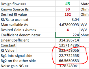
  • I did go on to check this setup using the tool I developed for matched impedance single to diff, looks like Figure 56 is set up correctly 

  • True. But then why does this schematic not provide the performance as shown in Figure 1 of the LMH5401 data sheet?

    If you have a minute, I also have a question about driving a capacitive load. Obviously driving a set of coax cables is the equivalent of driving a capacitive load. The data sheet implies that the output resistance built into the device is supposed to help alleviate this issue. I am assuming the matched 40 Ohm resistors on the output add to this as well. If that is not true, then how does one compensate for the capacitance of the coax cables? Network analyzer calibration won't do it because the impact, unless I am missing something, is on the performance of the LMH5401.

    Also, and I ave another thread going for this that no one seems to want to help on, how does this impact the performance of cascaded amps? We notice that cascading two LMH5401 amps causes an additional deterioration in performance. Is that because the input to the 2nd amp ends up adding a capacitive load to the output of the first stage?

    Thanks for your help on this.

  • Hi Ash,

    1. A coax cable does NOT mean a capacitive load, but a resistive load when using proper cable termination.

    2. Opening several posts about the same issue does NOT help but merely results in confusion.

    3. Doing in the 6GHz range is NO simple task. Do you have expensive semi-rigid coax cables? Do you have equipment allowing error-free measurements up to 10GHz?

    Kai

  • 1. Thanks.

    2. The other post is related but not the same issue. That one talks about the impact when cascading multiple LMH5401 amps. I only brought it up here because the narrowing of the bandwidth might have to do with capacitance on input of the the second amp looking like a capacitive load to the first amp.

    3. Yes to all of the equipment questions. In as far as not being a simple task, I'm fine with that. That's what we do for a living - non-simple stuff. ETA: We are a company that builds defense electronics for the DoD and have being doing this for 30+ years. We know RF. That's what we do for a living.

    My problem is that I can't get the results presented on the data sheet even with a TI-spice run on the EVM as delivered by TI for TINA. Here's what that looks like

    The 3 dB point is not 6GHZ!

    using their own sample for the EVM. So what am I missing?

    LMH5401 Eval.TSC

  • Maybe not exactly the same issue but my answers would be pretty much the same.

    This is no fun Frowning2

    Kai

  • Hi Ash,

    Your load is not 200 Ohms as the figure dictates. You are simulating 100 Ohms and comparing it to the 200 Ohms performance. 

    You can see the correct bandwidth with a 200 Ohm differential load.


    Best,
    Sam

  • May be, but not posted by me. That seems to have come from the TI customer support folks. 

  • Sam

    I'm missing something. The way you have it drawn the output load is 300 - 200 from R9 and R10, 80 from R6 and R7 and 10 ohms on each leg within the part. What am I missing?

    Also, I'm not sure what your cursor is showing at 6.01G. What is the 2.03 value?

    Thanks

  • So Ash, I am off the road (>6kmile roadtrip). 

    You are using the LMH5401 because you want DC coupled? If not, there are of course a myriad of RF amps that are wider band - even some differential output ones that I had been supporting some years back. 

    Of course when you cascade amplifiers the BW drops fast - the simple single pole cascade equation predicts a 36% drop from each stage separately. 

    The product group could just try to reproduce Figure 1 with current EVM material and that 4 port network analyzer. It is likely that the some details are missing that went into that plot.  It is surprisingly common to get plots that are difficult to reproduce outside the development lab - try doing a -145dBc HD measurement like on the THS4551 - proprietary technique. 

  • Michael,

    I'm actually looking at this amp for a couple of reasons - firstly it has a high input impedance which is what we need with our antenna (we've got a funky super high bandwidth antenna) and also the fact that I can produce a frequency dependent gain in the lower frequency regions. It's a whole thing that has to do with very wideband operation from a single antenna. Everything seems to work fine, except for the higher frequency roll off. But I finally have an answer here and may have to resort to some other amp for the later stages. Wish someone had just said this earlier instead of asking for schematic and stuff. Relaxed

    Have a good trip and thanks.

    Ash