This thread has been locked.

If you have a related question, please click the "Ask a related question" button in the top right corner. The newly created question will be automatically linked to this question.

AFE031: AFE031 powerline communications (PLC) analog front-end, FAILURE.

Part Number: AFE031

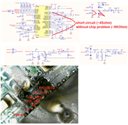
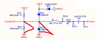
Dear Texas, we have a serious problem on several PLC chips (AFE031) after a few months of normal operation. Sometimes the transmitting stage doesn't work but only the receiving one, sometimes the whole chip. The problem would seem to be located on the outputs of the amplifier set from Rset to 1.6A (see schematic and burned chip photo attached). Please let us know as soon as possible if we have made any mistakes on the conditioning circuits or we need to reduce the transmit power output from the PA to solve the problem.

Best regards

Andrea vinci

  • Hi Andrea,

    It looks like that this is 230Vrms, 50Hz AC PLC operating condition based on your location. I still have several questions about your operation, before I am able to troubleshoot your application accurately. 

    1. What is a typical ambient operating temperature?

    2. What is your transmitted voltage swing, +/-12Vpp at 1.6Ap under 15V single supply rail? 12Vpp is equivalent to 4.24Vrms, say at 130-140kHz frequency. 

    3. What does this note apply? Do you mean that the damaged AFE031 has 45Ω DC resistance when as found in a short circuit. If the AFE031 is removed, the DC resistance is 8kΩ, which means that the PCB traces are likely partially shorted.  

    4. What is a typical DC operating current out of AFE031 when the application is transmitting or receiving PLC information?

    It looks like that you are using the reference design that is close to Figure 48 of the datasheet, which is based on AC PLC application for US, which AC power is operating at 115Vrms, 60Hz. 

    The following is my speculations about your issues. 

    a. AFE031 is operating at 1.6Ap (assume), which is a bit high. Yes, the AFE031 can transmit up to 12Vpp at 1.5Ap, which means that you will have a load 6Vp/1.5Vp=4Ω load. Can you verify your DC load after Pin 42 & pin 43.

    b. I will reduce the 470nf HV capacitor to 100nf or so on the AC PLC side. At 50Hz, the 470nf has impedance of 1/sC=1/(2*pi*50Hz*470nf)=6.77kΩ.If it is reduced to 0.1uf, its 50Hz impedance is increased to 31.8kΩ, which it will reduce the AC load at 50Hz. At high frequency, say 141kHz, 470nf's impedance is 2.4Ω and 100nf is 11.3Ω, which it should not attenuate the high frequency PLC operation. 

    With the reduced 470nf to 100nf, majority of 230Vrms voltage will drop across the capacitor. The remaining AC power will be reflected back across the coupling transformer.

    c. I believed that GND_X is an equivalent to neutral line in U.S., which is a different GND_F on the left side of transformer. This is AC power's safety issue,  not likely related to the burn out issue. I just want to mention it. 

    d.  What do these markings mean? Are they burned out or shorted as well. 

    e. I do not have enough information to say that AFE031 is damaged via overvoltage or overcurrent. At this point, I would speculate that AFE031's damage is due to over-current. Is it over current from 15V supply rail from AFE031 or over current that is reflected from coupling transformer from AC PLC side. Please provide me with the operating history. Was the AFE031 operating hot temperature environment for a period of time? Are there transient events occurred at the AC power side etc.?

    Please provide me with as much information as possible, so that I can troubleshoot your issues with reasonable confidence.

    In addition, this is public support forum. You may apply "friendship" request via E2E forum. After I am accepting your request, we are able to exchange information via private setting (E2E private message). 

    Best,

    Raymond 

  • Dear Raymond,

    It looks like that this is 230Vrms, 50Hz AC PLC operating condition based on your location. I still have several questions about your operation, before I am able to troubleshoot your application accurately. 

    - The voltage on the powerline is approximately equal to 250VDC continuous (230VAC @ 60Hz + transformer + graez bridge + capacitors).

    1. What is a typical ambient operating temperature? 30°C/35°C
    2. What is your transmitted voltage swing, +/-12Vpp at 1.6Ap under 15V single supply rail? 12Vpp is equivalent to 4.24Vrms, say at 130-140kHz frequency. 

    - I remember 6.8Vpp but I will take measurements and inform you promptly

     3. What does this note apply? Do you mean that the damaged AFE031 has 45Ω DC resistance when as found in a short circuit. If the AFE031 is removed, the DC resistance is 8kΩ, which means that the PCB traces are likely partially shorted.  

    - With a new AFE, R134, D24 all mounted, we measure about 8kΩ between TxLinePF (PA_out1 / 2) and GND_F. If the AFE is visually burnt (perforated), between TxLinePF (PA_out1 / 2) and GND_F we have a short circuit. If the AFE is not visually burned (perforated) and still communicates, between TxLinePF (PA_out1 / 2) and GND_F we have a resistance between 3 and 8 Kohm. If the AFE is not visually burnt (perforated) but does not communicate between TxLinePF (PA_out1 / 2) and GND_F we have a resistance of 45ohm about. It would appear that the impedance decreases over time.

    1. What is a typical DC operating current out of AFE031 when the application is transmitting or receiving PLC information? - I will take measurements and inform you promptly

    It looks like that you are using the reference design that is close to Figure 48 of the datasheet, which is based on AC PLC application for US, which AC power is operating at 115Vrms, 60Hz. 

    - No, we do not operate in alternating mode but in continuous at about 250VDC (plc bus).

    Can you verify your DC load after Pin 42 & pin 43.

    - The DC load is only that of the components placed before the capacitor. Yes, as soon as I can, I will measure this load

    With the reduced 470nf to 100nf, majority of 230Vrms voltage will drop across the capacitor. The remaining AC power will be reflected back across the coupling transformer.

    - Bus plc is 250VDC continuous not 230VAC

    I believed that GND_X is an equivalent to neutral line in U.S., which is a different GND_F on the left side of transformer. This is AC power's safety issue,  not likely related to the burn out issue. I just want to mention it. 

    - Bus plc is 250VDC continuous not 230VAC. GND_F is 0VDC potential of 250VDC

     What do these markings mean? Are they burned out or shorted as well. 

    - No, it means that I have measured the short on these components. Removing them the short remains because it is inside the chip.

    1. I do not have enough information to say that AFE031 is damaged via overvoltage or overcurrent. At this point, I would speculate that AFE031's damage is due to over-current. Is it over current from 15V supply rail from AFE031

    - 15VDC voltage is regulated by DC / DC converter.

    or over current that is reflected from coupling transformer from AC PLC side.

    - from transformer DC PLC side. Maybe!!!

    Please provide me with the operating history. Was the AFE031 operating hot temperature environment for a period of time?

    During commissioning is possible, until 40/50°C max, for a certain period.

     Are there transient events occurred at the AC power side etc.?

    - Are possible transient events occurred at the DC power side, for example when you connect power connector between one module end next module, or when occur a short circuit event… (our devices are protected from short circuit on the powerline bus).

    Please provide me with as much information as possible, so that I can troubleshoot your issues with reasonable confidence.

    - it will be done (can you give me an e-mail eventually for more confidencial circuit details).

    thank you very much for the support
    I'm waiting for your reply
    Andrea Vinci
  • Hi Andrea,

    Transformers do not pass direct current (DC). WE 750510476 is a standard transformer. When DC voltage is applied to the transformer, all the internal magnetic dipole material will orientate in a single direction, and acts like a shorted circuit. Therefore, AFE031 is likely damaged due to sourcing excessive current from the low voltage side. In addition, the transformer will likely be "hot" due to the configuration. 

    You may argue that you have capacitors placed on both end of the transformer. The issues are there are still DC voltage across the transformer (leakage from capacitor). The transformer is unable to "reset" its magnetic core to achieve volt-second balance in accordance with Faraday's law. When AC is passing a typical transformer (non-gapped), the residual magnetism in the core is changing per its BH curve. The residual magnetism will get "reset" in every AC cycle, so the magnetic core will not get saturate during operation. It may only take mA of DC current to saturate a typical transformer, if the input signal is DC voltage. 

    Transformer by definition does not have gapped core. You may be thinking about inductors that can pass some DC current and work with AC signals, such as switching power supply's inductor. The latter one is defined as inductor, which it has gapped core in its internal magnetic materials (weather it is a physical air gap or gapped with filler materials). The gapped inductors can take some amount of DC current depending on the characteristics of the core and materials, but it has a current limit when it is reached a magnetic saturation. 

    Here are two ways to couple AC signals onto DC powerline in PLC application. 

    1. capacitors can block DC and pass AC, so capacitor can be used to transmit AC signal and block DC voltage. If this is a low voltage application, I will recommend this particular coupling method. However, you have 250Vdc on the powerline side, this method may not work well for your application, since 250Vdc's return has to be isolated from the low voltage side of AFE031. 

    2. Alternative coupling method is using gapped inductor method. In schematic drawing, it looks like a transformer, but the gapped inductor has pass certain amount of DC current  without saturating the magnetic core. I do not know your current flow capacity on the 250Vdc side. Say you are working with 10Adc current on the 250Vdc DC side, the gapped inductor has to be rated up to 50A-100A range in order to avoid the core saturation under the worst case scenario (transient conditions, max. operating temperature etc.). The transmitted or received high frequency signals can pass through the gapped inductor and coupled onto the DC powerline.

    If you need additional assistant, please let me know. 

    Best,

    Raymond 

  • Hi Andrea,

    I am going to close this inquiry. Since we have established private E2E connection, you may ask questions via the private E2E forum.

    Best,

    Raymond