This thread has been locked.

If you have a related question, please click the "Ask a related question" button in the top right corner. The newly created question will be automatically linked to this question.

TLC339: The pulse was extended without reason from the input comparator to the output

Part Number: TLC339

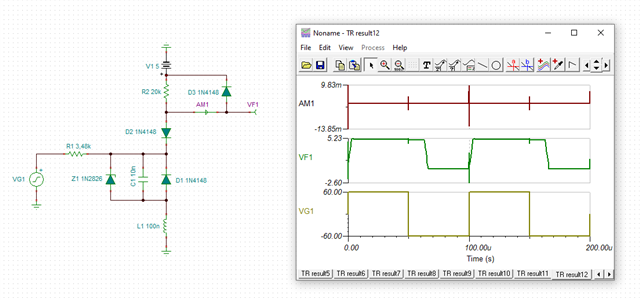
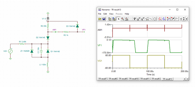
The pulse was extended without reason from the input comparator to the output (8msec pulse from the input has prolonged to 44 msec at the output).

Is there any answer/reason for that?


Recently, our system was failed because of 5 faulty components of TLC339IPW.

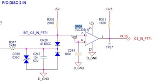
We enter at the input of the comparator (pin No 7) a  8msec pulse (logic level '0', from the initial and continuous state of '1').

We expected to get almost the same signal at the output (pin No 1), but in those faulty components, we got a pulse of about 44msec ('0'). When we replaced the faulty component with a new component the card worked ok. 

When we assembled these faulty components in a useable electronics card, the faulty situation has appeared.

Please see in the attached picture (below), the electronics circuit of one comparator in the Quad. The same electronics circuits are in the other three comparators.

Please see the date code of one of the faulty components.

  • Hi Shai,

    what is the circuit arround CR30 for? What voltage can be seen at the cathode of 1N4148?

    Do you exceed the common mode input voltage range of TLC339?

    Why don't you have any current limiting resistor at the inputs of TLC339? Insert 1k resistors directly at the input pins. Why don't you have the diode clamp connected to the supply voltage of TLC339?

    Kai

  • Hello Shai,

    Along with Kai's comments, what are the input voltage levels and the reference voltage level?

    Keep in mind that the TLC339 input range is Vcc-1.5, so the max valid input voltage would be 3.5V on a 5V supply. So a 5V input is out of range.

    Extended prop delay is a symptom of exceeding the input range or pulling the inputs below ground.

  • Thanks.

    CR30 for TVS suppressor. The voltage at the diode's cathode could be up to 5V.

    We understand that we are not allowed to exceed VCC-1.5V of the common-mode voltage input. 

    Could you recommend please a comperator in the same footprint that we can be allowed to exceed VCC-1.5V of the common-mode voltage input?

    We have a current limit by R317 (3.48K). The other open input is only for tests.

    Shai

  • Thanks.

    The input level might exceed VCC-1.5V of the common-mode voltage input. 

    Could you recommend please a comparator in the same footprint that we can be allowed to exceed VCC-1.5V of the common-mode voltage input?

    Shai

  • Hi Shai,

    and what is the turn-on voltage of TVS?

    Kai

  • Shai

    Since your operating voltage is only 5V, you can use one of our rail to rail input 5V devices such as TLV9044IPWR.  However, if you prefer to have the higher operating voltage range we also have the TLV1704AIPW which is also RRI.

    Chuck

  • The TVS is PSD36C.

    Turn-on voltage: Breakdown voltage is 40V (at 1mA), and Clamping voltage is 60V (at 1A).

    Shai.

  • Hi Shai,

    yes, everything seems to look fine. But when you add some inductance into the ground return current path introduced by a non-ideal layout, you will see dangerous spikes:

    Then a current limiting resistor directly at the input of TLC339 can work as a fire extinguisher:

    shai_tlc339.TSC

    I do always have such a current limiting resistor at the input of a CMOS comparator.

    The same is true for the -input of TLC339 where the Vref is connected to. If there are moments when the input voltage at this pin can exceed the supply voltage -think of power-downs-, the TLC339 will be damaged. So you should insert a 1k current limiting resistor here as well.

    Kai

  • Always a great point to bring up.  Thanks Kai

    One thing worth adding is that not all devices have the traditional ESD protection diode to the VCC pin.  For these devices, limiting the current always helps but it may not save you.  These devices have a snapback protection circuit and for these devices you need to have external protection to limit the voltage.  These devices are identified by looking at the abs max table.  The device input voltage has an absolute voltage rating instead of a VCC+0.3V like spec.

    Chuck

  • How can we start the process with TI of sending some faulty components for investigation of the malfunction?

  • Shai

    you would need to contact your local TI representative to return devices for Failure Analysis.

    Chuck