This thread has been locked.

If you have a related question, please click the "Ask a related question" button in the top right corner. The newly created question will be automatically linked to this question.

TPA3128D2: Power on/off clicking noise (stepping bias voltage) on the outputs when using 1SPW mode. No problems in BD mode

Part Number: TPA3128D2
Other Parts Discussed in Thread: TPA3132D2, TPA3118D2, TPA3116D2, TPA3130D2, TPA3131D2

I'm having some issues with a new TPA3128D2 implementation when using 1SPW mode. When powering the device on (with open inputs) i can hear a clicking sound on the outputs which refers to stepped bias response on the inputs.

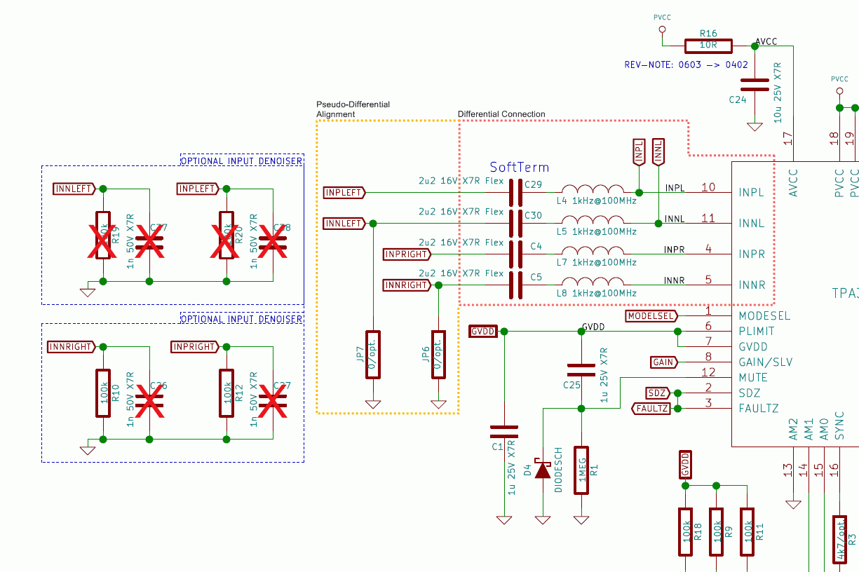
IC is configured as:

600kHz 1SPW
SE input (ground refered)
2u2F input coupling caps
1s power on mute
Weak 100k "pulldown" resistor to GND on the inputs before coupling-caps
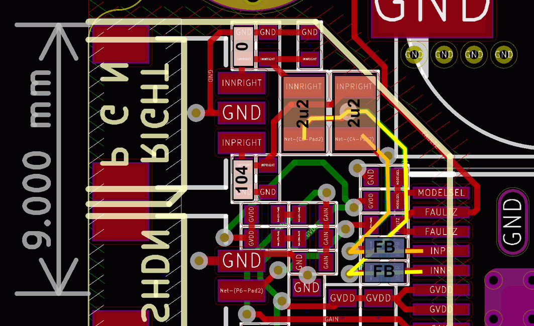
System overview:

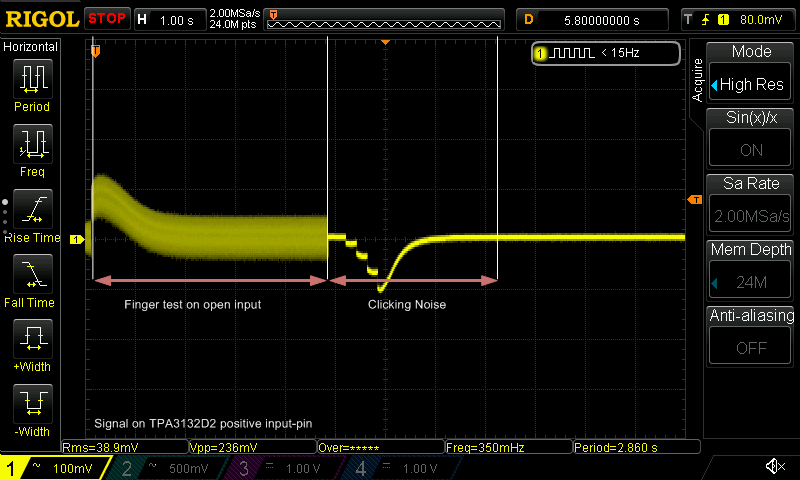
The clicking noise looks like this on power on:

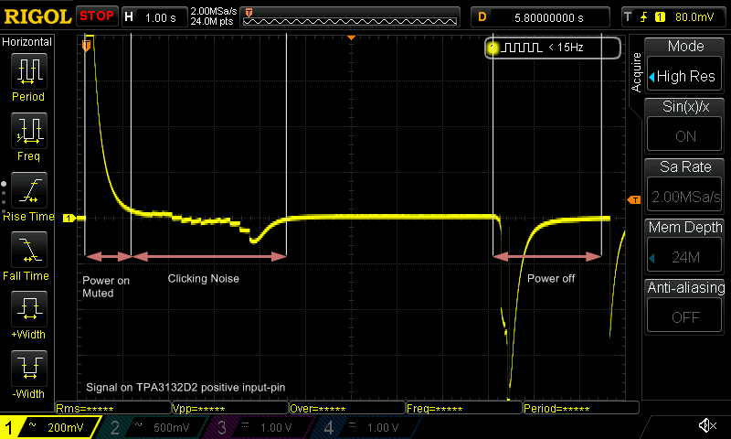
Touching the inputs while powered on also results in clikcing noise as shown here:

As said, this isn't noticeable when using BD modulation. Any ideas?

Best regards,

Christian

www.360customs.de

  • Hi Christian,

    Are you using the differential input mode or single-ended mode? Pop noise can be mitigated in differential mode.If you have to use single-ended mode, please use pseudo-differential input in your PCB layout design. And please make sure the differential input route is symmetrical. Any mismatching could cause pop noise.

    Is there any buffer or somthing between DAC output and the audio amplifier input? Please don't use any of them in front of TPA3128D2 input, because they are actually not necessary and they probably cause mismatching on the differential input. How much input capacitors are you using? Please use 1uF/0.47uF capacitors for them.

    There shoudn't be any pop noise if the application design is appropriate for TPA3128D2. You are right that it's more sensitive to pop noise in 1SPW mode, comparing to BD mode. Becasue the input DC common mode voltage setup process is different between these two modes.

    Best regards,

    Shawn Zheng


  • Hi Shawn,

    thanks for the answer. I indeed use single-ended mode in pseudo-differential design, so negative input in tied to ground in front of the coupling cap. The differential routes are as symmetrical as possible. The phenomenon is not like classic pop-noise like power-on pop without muted output but mode like clicks as expected from the scope plots as the dc-bias is stepped. The tests where made with open inputs, no buffer oder DAC connected. When connecting a source with active output stage, there isn't any noise at all but clicking can then be notices when the source is powering down its output stage. (Like on a mobile or bluetooth dac with powersave-mode)

    There are 4 capacitors in place right now with 2u2F. With 26dB gain (30k input impedance), the f-3dB is at 2.4Hz. 1uF should also do with f-3dB at around 5.5Hz. (Minus DC-bias reduction due to X7R ceramic) From measurements in the past, MLCC is prone to increase noise at the lower end of the audio band, so shifiting the f-3dB very low gives a bit of advantage but this is not part of the problem here.

    What's happening while the CM voltage setup? It looks like stairchasing to the final value.

    Please see the following print for the audio-routing. The ferrite beads don't do anything here, they're Z=1000R@100Mhz and have a DCR=1R max. The INP is terminated by 100k on the input to supress static charge.

    Best regards,

    Christian

    www.360customs.de

  • Hi Christian,
    Thank you for the detailed explanation.
    1uF input capacitors needsless time to charge, then decreasing the common voltage setup time. So the pop noise is lower with 1uF input capacitors, comparing to 2.2uF.
    I think another way you can try to minimize the pop noise in 1SPW mode is to use SDZ instead of to MUTE to control the output of the device. In SDZ operation, the charging current is larger than MUTE. So a low pop noise could be achieved by using SDZ to control the output.
    100KOhm resistor on INP probably introduces mismatch on the differential input. Please make sure the differential input is symmetrical.
    About the DC common voltage setup in 1SPW mode, it's something like stair as you described. Normally it doesn't cause pop noise as soon as there is no mismatch on the differential input.
    Best regards,
    Shawn Zheng
  • Hi Shawn,

    thanks foe your reply. May i ask how the 100k introduce more imbalance to the pseudo-differential-alignment then the GND-connection of the negative inputs alone? The pseudo-differential-alignment is an imbalance per definition, is it not? To make thinks for more clear, please see the following annotation for the actual setup:

    With open inputs, the imbalance would be much higher than with 100k, no? Is it possible to match the connected source with JP7 and JP6 if i know the output impedance of the source?

    NOTE: The FAULTZ pull-up resistor is not shown

    Best regards,

    Christian

  • Hi Christian,

    Yes, your understanding is correct. From your SCH, I think 100kOhm shouldn't introduce imbalance, sorry for my misunderstanding -  I couldn't see it from PCB layout very clearly, and I thought there is imblance on INP and INN.

    If there is any other question or anything unclear, please free feel to let me know.

    Best regards,

    Shawn Zheng

  • HI Shawn,

    thanks for the answer. To sum the problem/solution up:

    - 1SPW does not work "great"/pop-free with coupling caps greater than 470nF - for a given input impedance of 30kR

    - High-Z ferrite beads doesn't affect the problem/solution

    - 100k+ on inputs (decoupled side) wont introduce imbalance

    - using SHDN/SDZ rather then MUTE at power-up helps due to higher "precharge current" to set the bias voltage

    - if using SHDN/SDZ, direct connection to FAULT must be altered work properly

    - when using MUTE at power-up with some time-constant, this must be increased for lower power-on-delay

    - always use fully differential drive if possible

    - all the above does not change noise/pop performance while powered for re-setting the inputs from a bias mismatch

    - Behavior is possibly getting better when driving the inputs differential (TBD)

    Best regards,

    Christian

    Edit:

    Does this also applies for TPA3116D2, TPA3118D2 and TPA3132D2? I suspect 1SPW (pre TPA3128D2) and "Hybrid Mode" (TPA3128D2) to be the same?

  • Hi Christian,

    Thank you very much for the great summarization. '1SPW mode' is close to 'Hybrid mode', but not totally the same. Just from the pop performance point of view, you could say they are the same, because the cause of the pop noise is the same. So the rules you summarized above also applied for TPA3116D2, TPA3118D2, TPA3130D2, TPA3132D2, TPA3131D2. But please keep in mind that, the best way to avoid pop issue in an appication is to use differential input mode and make sure the symmetry on the differential input route.

    Best regards,

    Shawn Zheng  

  • Hello Christian! Did this answer your question? Thanks, Jeff
  • Hi Shawn,

    thanks for the follow up. Of course, differential drive is the best, but if a product states "pseudo differential" capability if should work like noted in the datasheet. :-) From our own measurements we know that the TPA31XX is performing "much worse" in "pseudo-differential" compared to fully differential. I wonder why this isn't shown clearly in the datasheet, beside the fact that MUTE and SHDN provides different charge times for intermediate voltage levels and the fact 1SPW needs more delay time. So we're a bit unhappy with the informations provided with the datasheet/application notes as pop/noise problems come up now and then and even the e2e forum is full of related questions.

    For the moment i'm fine with the informations (even if if have more questions in detail, i.e. what exactly is the difference between 1SPW and Hybrid beside the marketing aspect).

    Best regards,

    Christian

    www.360customs.de