Hi team,
The customer is using INA301A3-Q1.Gain=100. His load current is 5mA. And he use 3.3V power supply. His Rsense is set to 200 mohm.
Please check his schematic in the fig 1. His issue is the ALERT pin always outputs the low level.
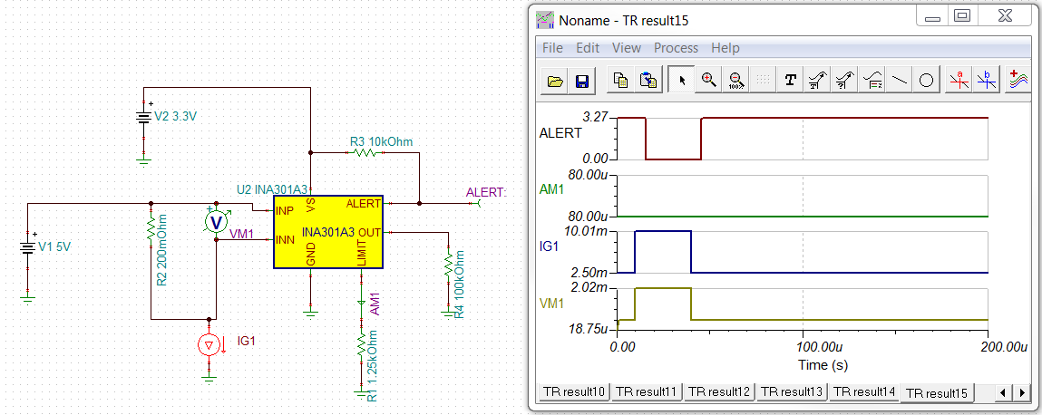
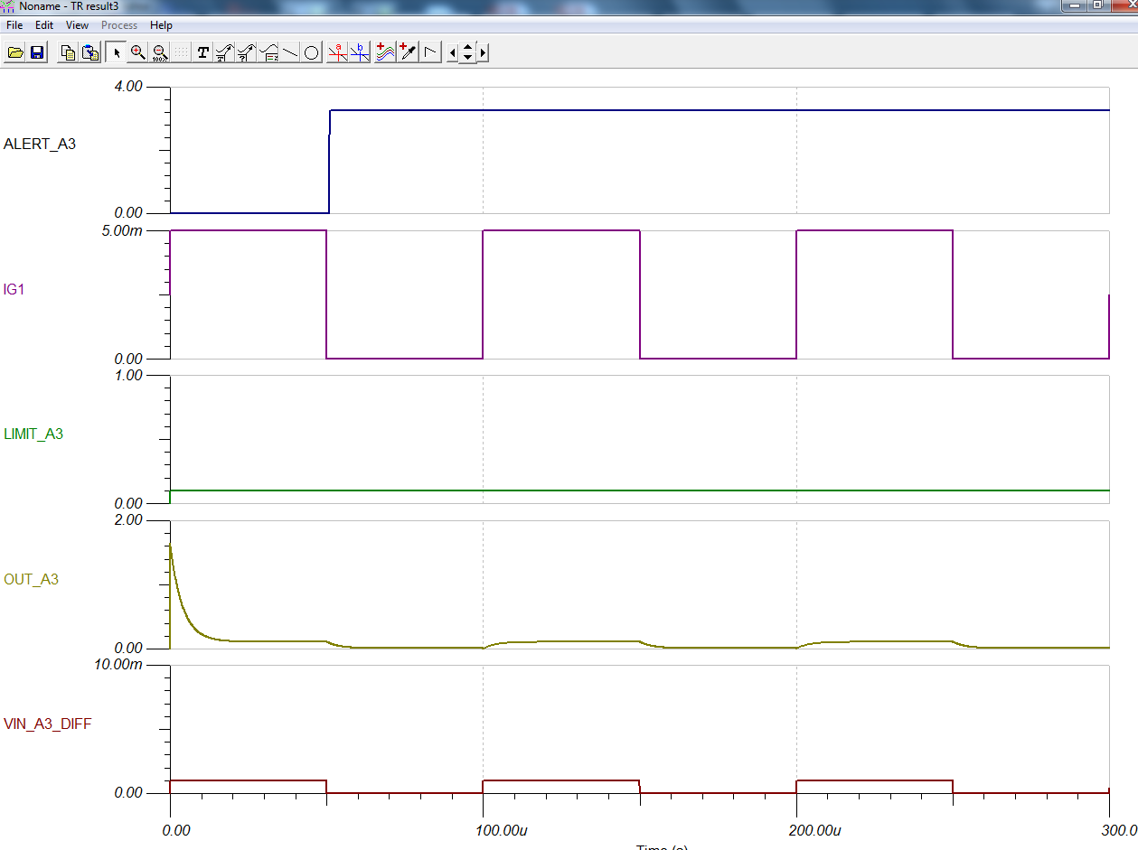
I also do a TINA circuit and do a transient with the zero initial values condition. Please check the fig 2 and fig 3.
For the customer's issue, would you provide some suggestions and send me a correct TINA circuit?
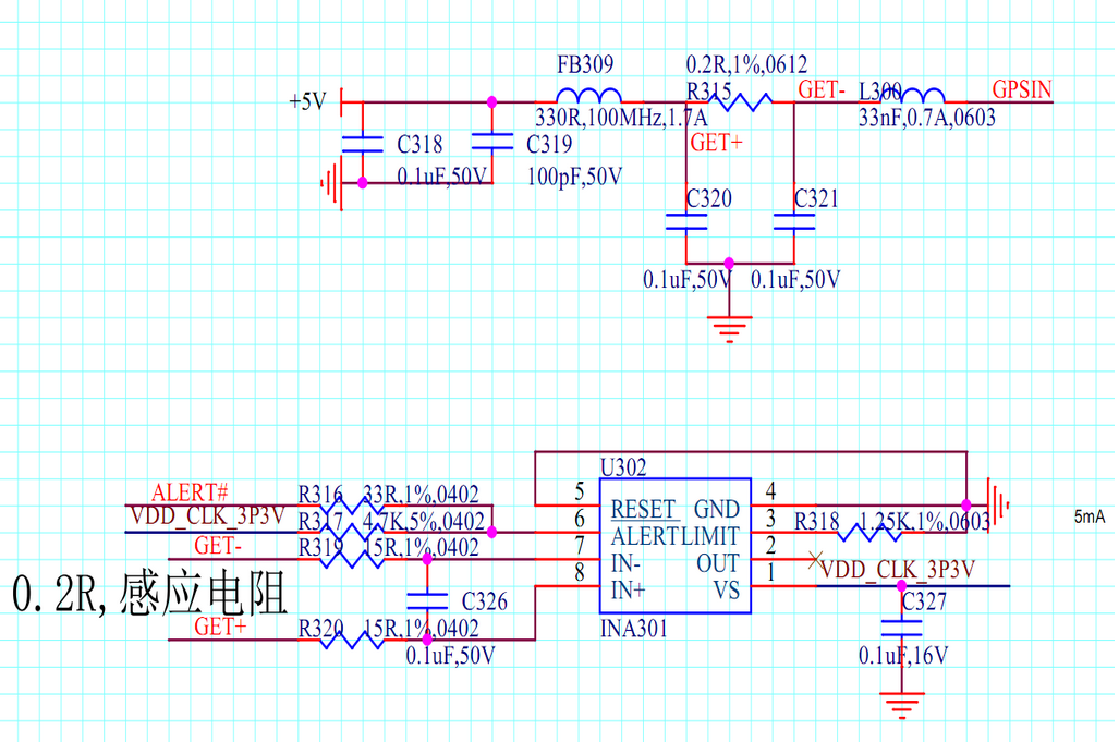
fig 1
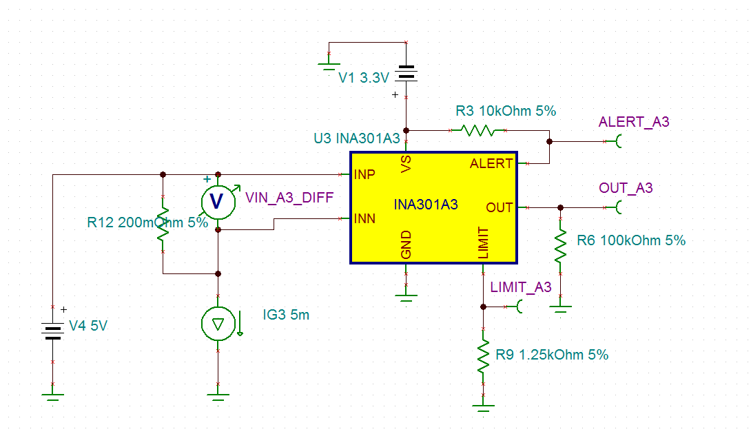
Fig 2
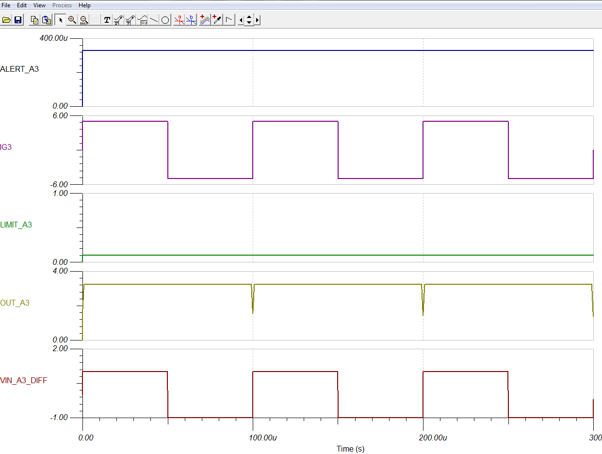
fig 3
Best Wishes,
Mickey Zhang
Asia Customer Support Center
Texas Instruments