This thread has been locked.

If you have a related question, please click the "Ask a related question" button in the top right corner. The newly created question will be automatically linked to this question.

INA138-Q1: INA138 does not have inverted battery protection, when it is used to measure the charge current to a battery.

Part Number: INA138-Q1
Other Parts Discussed in Thread: INA138, INA240, SM74611, LM74610-Q1, LM74700-Q1

Hi,

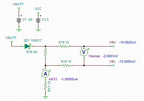
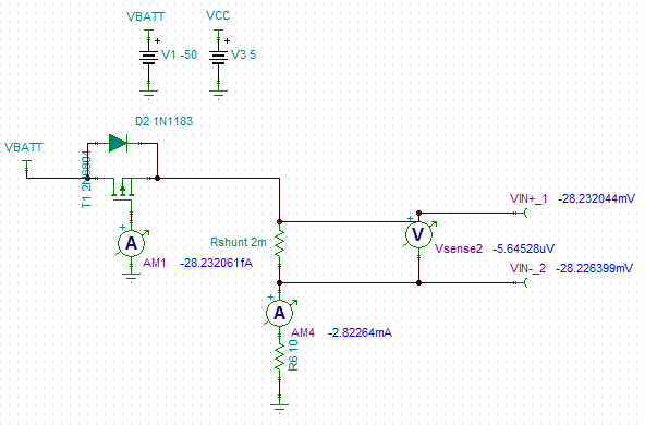
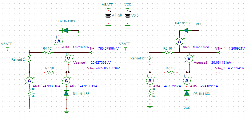
I am using the IC to sense the charge current of a battery, but if by mistake the battery is inverted the IC is damaged.
I can add two resistors to the measurement input of the same value to avoid the short circuit.
Or what do you recommend?

  • Hello Reinaldo,

    I will have to get back to you tomorrow after talking with my team, but it seems you would want some diodes fromt the IN+ and IN- pins to ground to clamp the common mode voltage or you could use a MOSFET to completely open the circuit.

    What is the value of the current being measured? This will limit what parts can be used.

    Best Regards,
    Peter Iliya
  • Hi Peter,

    It seems that there are diodes between GND (anode) and VIN- and VIN + (cathodes), which causes an excessive current between GND and VIN- when the battery is inverted. The maximum current is 5A.

    Thanks.

    Regards,

    Reinaldo García.

  • Hey Reinaldo,


    I am assuming that you want to prevent the common-mode voltage of the INA138-Q1 to not go below -0.3V, which would happen if the battery is placed incorrectly with the reverse polarity.


    The very high currents are definitely a problem and could be limited with some current-limiting resistors placed in the input traces into the IN+ and IN- pins of the INA138-Q1 device; however, placing these resistors (even if around 10Ohms) will starts producing error in the INA138 measurements. We as a rule limit these resistors to nothing greater than 10 Ohms, but if you are willing to sacrifice accuracy you could increase this value, see Option 3.


    Option 1 – Use a single diode in the power path


    During normal operation you will lose power supplied by the battery according to the forward voltage drop of the diode used. If the battery is incorrectly placed, then diode is reverse biased and will open up the circuit. A Schottky diode would work best here because it could provide the lowest forward voltage drop during normal operation, but you will want to make sure that it can withstand the reverse bias voltage (the battery’s voltage).


    Option 2 – Use PMOS FET in the power path

    http://www.ti.com/jp/lit/an/slva139/slva139.pdf


    Option 3 – Use 2 normal rectifying shunt diodes off IN+ and IN- inputs


    This is a straightforward approach where you place two 10-Ohm, current-limiting resistors and then shunt diodes from the IN-/IN+ pin to ground (left circuit) or to the voltage supply (right circuit). The common-mode voltage will be clamped to {VDD - Vf} where Vf is diode foward voltage drop. The problem is the diode current will be high (~5A) if battery is misplaced. It would be up to your power voltage supply (INA138 VCC) to supply this current.


     If you connect the anodes to ground (left circuit), then it is up to the battery to supply this current. With this diode biasing, the common-mode voltage will become clamped to the forward diode drop. You would need to find a diode with the lowest possible diode drop (<0.3V), but at the same time a reverse-bias max voltage greater than your battery’s voltage.


    The secondary problem with this high current is that your current-limiting resistors (R4, R3) will need to be able to dissipate that power. If these resistors are increased to 50 Ohms, the diode current drops to ~1 A and it seems there are resistors that can handle this power dissipation. Although I am not sure how much accuracy you need to retain for your system. The error produced by input resistors (R4 = R10 = Rin) is due to the input offset current (Ios) generating a voltage offset on top of you shunt voltage signal. This offset error is:


    Ios*Rin = (IB+ - IB-)*Rin.


    As your shunt voltage increases so does Ios because, the IB+ and IB- curves usually diverge from one another. We do not have this characterized for INA138 as we do with other devices unfortunately (see INA240 datahsheet), but it can be measured with an ammeter in series with the inputs, while the input voltage is increased.


    Option 4 – Use Zener and Rectifying diodes


    This relies on the fact that Vz and Vd are chosen carefully. The common-mode will be clamped to VCC – Vd – Vz. At the 5A running through the diodes, Vz = 4.189V and Vd = 0.785, so with the power supply at 5V, the VCM becomes 26mV (within INA138 CM absolute maximum rating).


    Option 5 – Implement a comparator that will turn a MOSFET off if reverse polarity detected

    You can read more about this in a former post here:


    NegVCM_normalDiode.TSC

    SingleSchottky.TSC

    PMOS_FET_inPath.TSC

    Zener&Normal.TSC


    Hope this helps.

    Peter Iliya

    Current Sensing Applications Support

  • Hi Peter,

    We need a solution more simple and cheap.

    Thanks.

    Regards,

    Reinaldo García.

  • Hey Reinaldo,

    What are you trying to protect? Are you trying to protect the INA138 from a common-mode voltage less than -0.3V or are you trying to protect all of the circuitry from the reverse polarity of the battery?

    What was the original purpose of the diodes off the inputs? Was this to clamp the input common mode voltage similarly to Option 3 above?

    What is the voltage of the battery? What is supplying power to the INA138? Is the battery powering the INA138 indirectly?

    The options I listed in previous post have been the common way to protect against battery polarity reversal, thus I am not sure there are cheaper ways. There certainly are simpler methods like using performance/smart diode ICs such as the LM74700-Q1, LM74610-Q1, or the SM74611, but these are likely going to present a similar or higher price point.

    Sincerely,
    Peter Iliya
    Current Sensing Applications

  • Hi Peter.


    I think the initial problem has not been explained well. At firts if one of the applications of the INA138 is to measure the current of a battery charger, when inverting the battery there is a current of GND to -VIN (INA138) which would damage the INA138. This is the problem.

  • Hey Reinaldo,

    The reason there is excessive current is because if battery is misplaced, then the common-mode voltage (or -VIN) becomes a negative voltage (equal to battery voltage) that is much more negative than INA138's -0.3V absolute maximum limit. Once this happens, there is an internal ESD diode that goes from -VIN (cathode) to INA138 ground (anode) and this diode become foward biased. Once the internal ESD diode becomes foward biased, it conducts a very high current (>>10mA) and begins to heat up, which will cause damage to the part. you can read about this here: e2e.ti.com/.../3599.exceeding-the-absolute-maximum-voltage-ratings-specifications-by-limiting-input-current


    You could try to limit this current to less than 10mA with current-limiting resistors on the inputs of the INA138, but this simply won't work without seriously decreasing the device accuracy. You could then try using diodes to clamp the inputs at some valid common-mode voltage (Options 3 and 4 above), but you still need to limit the current somewhat and posses a power source for the INA138 that can even source this current. Or you could try just protecting your entire system from the reverse polarity (Options 1 and 2 above).

    If you have any schematics and rather not share them on the forum, you can email me directly at p-iliya@ti.com.

    Sincerely,
    Peter Iliya
    Current Sensing Applications