Other Parts Discussed in Thread: TINA-TI,
How do I use the closed loop output impedance (Zout) to stabilize the output of a current sense amplifier with a capacitive load?

This thread has been locked.
If you have a related question, please click the "Ask a related question" button in the top right corner. The newly created question will be automatically linked to this question.
This post is a shorter version of the application note Closed-Loop Analysis of Load-Induced Amplifier Stability Issues Using ZOUT.
Capacitive loads degrade amplifier stability. In most cases, loading an amplifier with a capacitor causes its output to ring or oscillate. The traditional method for evaluating the impact of a load capacitor on the stability of an amplifier involves analyzing Bode plots of the amplifier’s loaded loop gain function. The load capacitor interacts with the amplifier’s open-loop output impedance (ZO) to introduce additional poles in its loop gain. The locations of these new poles relative to the pole frequencies of the amplifier’s unloaded loop gain determine the available stability margins.
However, measuring loop gain requires “breaking” the amplifier’s feedback loop, and this is not possible in the case of closed-loop amplifier ICs such as current-sense amplifiers. This is because the feedback loop is internal to the IC and cannot be manipulated.
Nevertheless, there is a closed-loop amplifier property that is affected by changes to loop gain and can be used for stability analysis without breaking the loop. This property is the amplifier’s closed-loop output impedance (ZOUT), which is becoming an increasingly common specification in the datasheets and SPICE macro-models of TI current sensing products. This post demonstrates through TINA-TI SPICE simulations how ZOUT information can be used to predict the capacitive load stability of closed-loop current sense amplifiers.
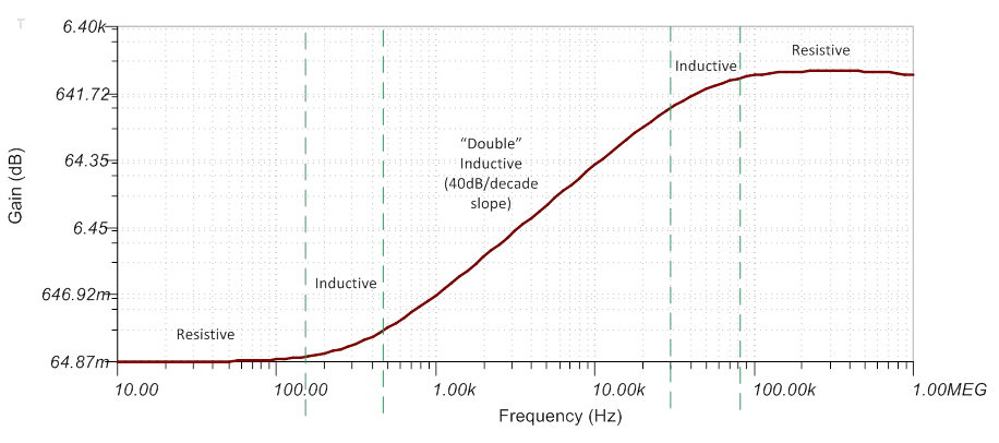
The INA199 has an inductive output impedance (ZOUT) characteristic over a wide frequency range. As a result, it resonates with most cap loads (greater than 1nF) and produces an unstable load transient response. Adding series resistance makes the output impedance more resistive at lower frequencies and improves stability when the INA is loaded with sufficiently large cap values.
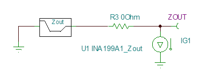
The INA199 ZOUT magnitude (Ohm) vs. frequency curve shown below is based on typical units that we measured under nominal supply and temperature conditions. The ZOUT test circuit (figure 1) is shown below as well as the plot (figure 2).
|
|
| Figure 1. INA199 Tina simulation test circuit |
|
|
| Figure 2. Typical INA199 ZOUT magnitude (Ohm) vs. frequency curve |
From the above plot (figure 2), ZOUT is inductive over the frequency range between approximately 150Hz and 80kHz, with impedance magnitudes between 100mOhm and 1kOhm. Therefore, any capacitive load whose impedance is between 100mOhm and 1kOhm over this frequency range resonates with ZOUT.
For example, the impedance vs. frequency plot below indicates that the INA199 will oscillate for 100nF and 1uF loads, but not for 250pF or 1nF. The corresponding load step responses more or less confirm this, although the model does produce some ringing with a 1nF load.
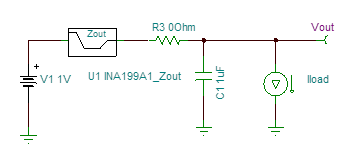 |
| Figure 3. INA199 simulation test circuit with load capacitance and 0 Ohm output series resistance to show resonance |
 |
| Figure 4. The INA199 test circuit from Figure 3 with different load capacitances on the output and how the ZOUT curves intersect |
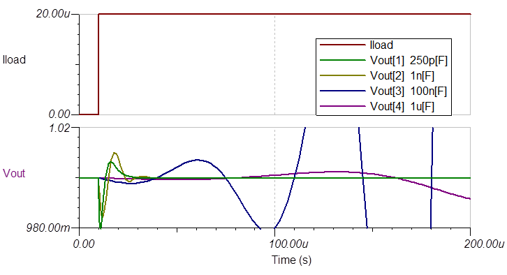 |
| Figure 5. How the output of the INA199 test circuit shows resonance with the different load capacitances after a step input |
As mentioned earlier, increasing the series resistance at the INA output makes ZOUT more resistive over frequency (as seen in the figures 6 and 7 below) and improves stability against large cap loads.
 |
| Figure 6. INA199 simulation test circuit for evaluating different R3 values |
 |
| Figure 7. Output of test circuit in figure 6 with purely resistive loads and how the ZOUT curve changes. |
In fact, adding a 200ohm series resistor is sufficient for driving loads between 100nF and 1uF.
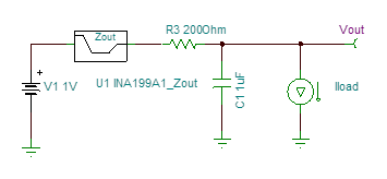 |
| Figure 8. INA199 simulation test circuit with 200 Ohms and various capacitances with an input step |
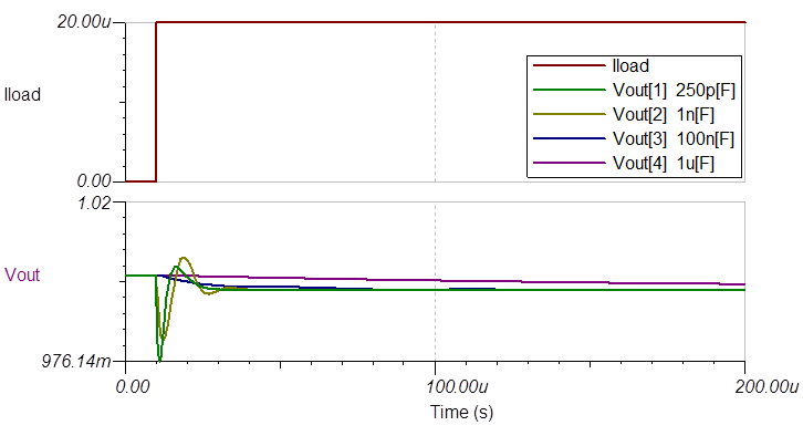 |
| Figure 9. How the INA199 settles to final output values quickly without oscillation or resonance because of the included series resistance. |
Use of the closed-loop output impedance (ZOUT) curves and profiles of capacitor and resistor filter networks can help drive values for output filter design that will result in fast-settling, stable output signals.
For even more information on this topic, please read Modeling the output impedance of an op amp for stability analysis in the Analog Applications Journal
TI makes no warranties and assumes no liability for applications assistance or customer product design. You are fully responsible for all design decisions and engineering with regard to your products, including decisions relating to application of TI products. By providing technical information, TI does not intend to offer or provide engineering services or advice concerning your designs.