This thread has been locked.

If you have a related question, please click the "Ask a related question" button in the top right corner. The newly created question will be automatically linked to this question.

INA196: INA196 issue

Part Number: INA196
Other Parts Discussed in Thread: LMC6482

Hi

I'm using the INA196 to sense the current of my DC/DC stage. I have to change the output voltage from 0V up to 52V.

I have two issues:

1) Feedback voltage to the current sense resistor

When I set the output voltage to Vo = 0V, the INA196 drives a voltage to the current sense resister (around 0.6V). Is this an issue because this IC is not able to work with 0V at the output?

2) Output voltage can't drive the Opamp circuit

I use an Opamp circuit after the INA196. I don't know why, but the output of the INA196 will be pulled up (over 10k resistor) instead he stays at the current level. I could solve this issue by adding a buffer. But I think that shouldn't be.

Thanks for your help.

BR

Silvano

  • Hello Silvano,

    Thank you for considering to use Texas Instruments in your design.  There are a few points I need clarification on.  You say your output is 0V to 52V.  I am assuming this corresponds to the INA196 voltage output.  If so, you will damage the device.  Output is limited to 18.3V max, assuming a supply of 18V.   When you say you set the output to 0V, are you setting Vsense to 0V, Vsupply to 0V, or driving the output to 0V regardless of the Vsense voltage?  If you are doing the last of the above mentioned methods, you likely damaged or will damage your device.  The reason is that while you set your Vout to 0V, the device internally is setting Vout to Vsense*20V/V, thereby making the device run potentially a lot of current through the output impedance, (Vsense*20-0V)/(small Rvalue).

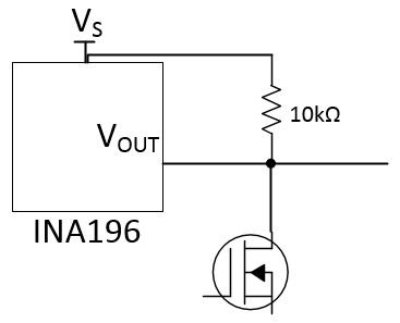
    In this last sentence, did you mean to say you are unable to pull up the INA196 output?  If so, you will not be able to pull up this device as it is not an open drain output.  Also, even if you have an external open drain like below, the INA196 is still going to drive the output.

    If I completely misinterpreted what you said, please post a basic block diagram of what you are doing, so we can quickly assess what your problem may be.

  • Hi Patrick

    Thanks for the fast replay. I have to explain it more clearly as I have done. Sorry my fault.

    This is the block diagram. I generate a voltage with the DC/DC stage from 7 to 52V. After that I have a LDO to bring the voltage down between 0 and 52V (Vout). Now I need to measure the current in this power train. For that I would like to use the INA196.

    Back to the Problem.

    1. If I use the shunt at this position, the INA196 delivers a voltage (around 0.6V) back to the sense lines. So in the case that I would like to set Vout to 0V, it remains around 0.6V driven by the INA196. I suppose that the INA196 is not able to sense the current over the shunt it Vout is too low. Is this correct?

    2. The output of the INA196 goes into an OpAmp circuit with an impedance around 10kOhm. (basic subtractor circuit). Because of a reason that I don't understand, the output of the INA196 can't stay at the level which representing the current. It will be pulled up by the OpAmp circuit. If I disconnect the OpAmp circuit, the INA196 output works fine. So I don't understand how that can happen. The only point that I could imagine is, that the output of the INA196 can't drive almost no current. But that makes no sense.

    I hope it is more clear know. Thanks for your help.

    BR

    Silvano  
  • Hello Silvano,

    Can you try posting your block diagram again?
  • Hello Silvano,

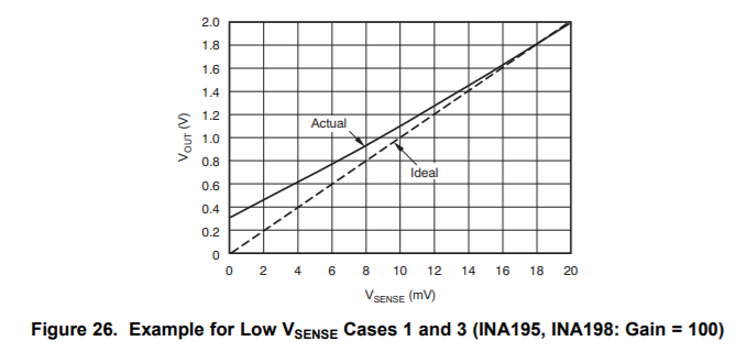
    Thank you for posting that.  I better understand your circuit now.  Unfortunately the output will  never reach 0V, even if Vsense is 0V.  This can be observed in the figure below taken from the datasheet.  You may want to consider a different device if you cannot ensure that your Vsense min is greater than  20mV.

    As for what you are seeing with op amp, that seems unexpected.  Did you try swapping that op amp with another?  Perhaps the op-amp is broken.   I will need to look more into that.  Which op amp are you using?

  • Hi Patrick

    1. Point

    Sorry you get me wrong. I'm talking about Vout related to my drawing and not the output of the INA196. Concerning the output offset of the INA196. I understand it. I should be able to manage it.

    2. Point

    I'm using a LMC6482 with a resistor to the negative input of the OpAmp of 10k.

    Do you suggest an other current sense monitor IC from TI?

    BR

    Silvano

  • Hello Silvano,

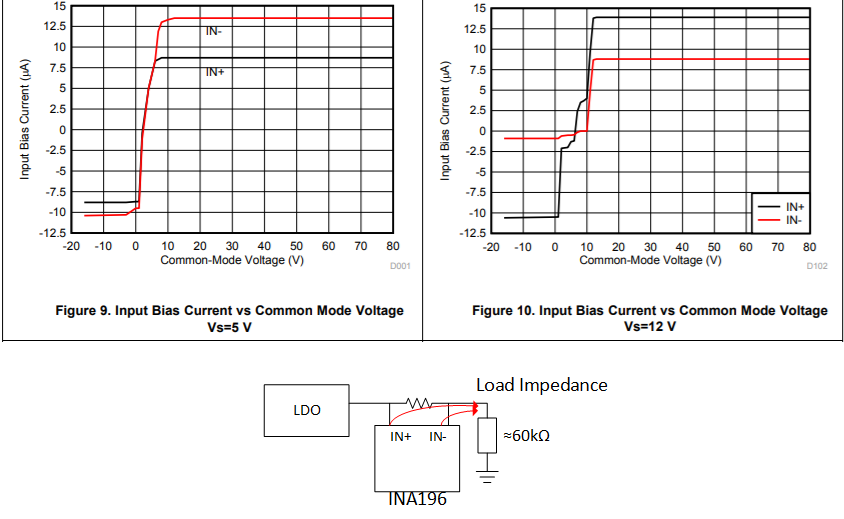
    I believe I may have an explanation for point 1.  I believe the 0.6V you are seeing can be attributed to the the INA196 input bias current.  According to our datasheet at a low VCM (when you set your LDO output to 0V), the part begins to source current.  If you have a large impedance to ground from this point, the sourced current could potentially create this offset.

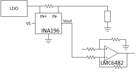
    For point 2, perhaps there is a problem with the LMC6482.  Have you tried driving that input separately with a different source?  I presume your setup looks something like this, correct me if I am wrong.

    To recommend a part, I need to know what voltage you intend to use for your supply and the amount of current you intend to measure.  What value shunt are you using?

  • Hi  Patrick

    Point 1

    It sounds logical but the load that I use is around 4.3kOhm. But perhaps it is something in the path back. Anyway the reason why I have to bring the voltage over the load down to 0V is, that I have to ensure that the load has no power anymore (heater) to heat up the system. So anyway I have to be sure that even this Iq current (total around 20uA) haven't to flow into the load.

    I will solve this issue by moving the shunt to the input of the LDO (Do you remember: DC/DC stage, LDO than load. So in this case I can measure the output current without adding any current on it. So this I have already tested and it works.

    But thanks for the explanation. It always good to understand the situation better.

    Point 2

    I didn't try to drive with an other source. I can check that. Perhaps you are right and it is an issue with the LMC6482 or with the build of the circuit. (hand made) But what I have to say is, yes the circuit that I use is exactly as you have shown but to solve this issue by now, I just have added a voltage follower as buffer with a LMC6482 after the INA196 and than it works fine.

    I'm using a 9mOhm shunt and I drive up to 8.5A. I need this current information for current sharing (but only important at higher current level) and for the current limitation.

    Thanks for the help.

    BR

    Silvano 

  • Hello Silvano,

    Based off of the details provided above I do not think we have a better alternative to suggest to you at the moment. Several alternative devices have similar input bias current profiles at lower Vcm voltages. Additionally with a max Vcm of 52V there are fewer devices to choose from. So I am glad that you were able to find a workaround to get your system functioning closer to what you want. If you observe further undesirable device behavior or if you need additional support, please let me know.