Dear Sir,
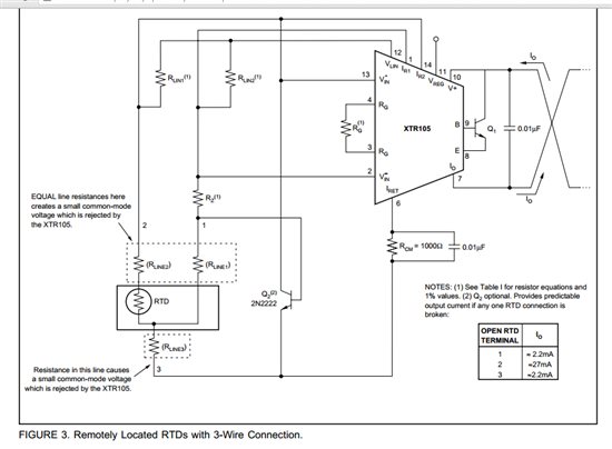
Attached is the complete schematic borrowed from the XTR105 datasheet and assembled on a PCB. The input to the same is PT 100 3 wire RTD, and the temp range is 0-150 degree Celsius. We are facing a problem with the IC's lead resistance compensation for 3 wire PT100 RTD.
With no lead resistance i get a correct output as follows:
for 0 degree = 4mA
for 150 degree=20mA
But when a "LEAD RESISTANCE" of "4.7ohms" is connected it gives me following error in output:
for 0 degree = 6.64mA
for 150 degree=22.45mA
In the datasheet it is mentioned that the XTR105 provides compensation for the lead wire resistance. The circuit diagram borrowed from the datasheet is FIGURE No.3 on PAGE 10. We have verified the resistances of the 3 lead wires, they are as (4.78, 4.79, 4.95 ohms).
We checked signals on every pin of the IC with an Oscilloscope. They are all clean / zero noise.
Following are some observations:
1. The voltage each of the Pin Nos. 1, 14, 2, 13, 3 and 4 rise from 1.79V to 1.92V after connection of lead resistance.
2. The voltage on Pin no. 8 rises from 0.35V to 0.95V after connection of lead resistance.
3. The voltage on Pin no. 9 rises from 0.85V to 1.473V after connection of lead resistance.
The above voltages are measured with respect to ground potential.
Similarly voltages on other pins i.e on 6, 12 and 11 also rise after we connect lead resistance to it. This time the lead resistance value is of 10 ohms +/- 0.2 ohm on RTD points A, B, C.
Kindly suggest a solution.
Regards,


