Other Parts Discussed in Thread: TLV9062, TLV3201, TLV3541, OPA684, OPA350
Hello everyone,
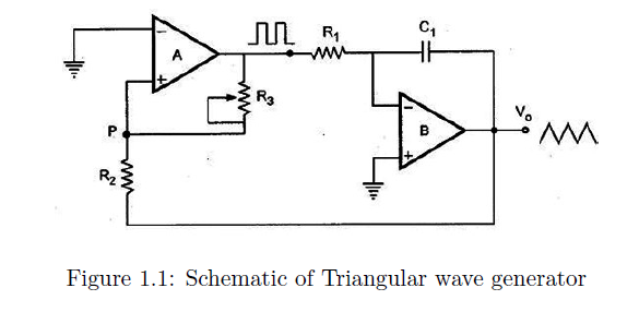
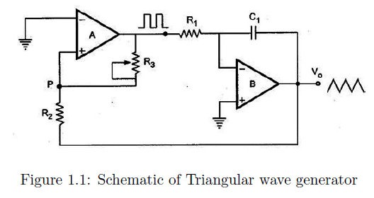
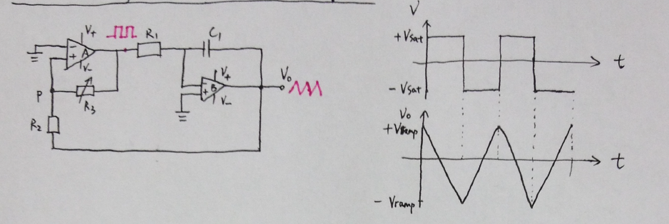
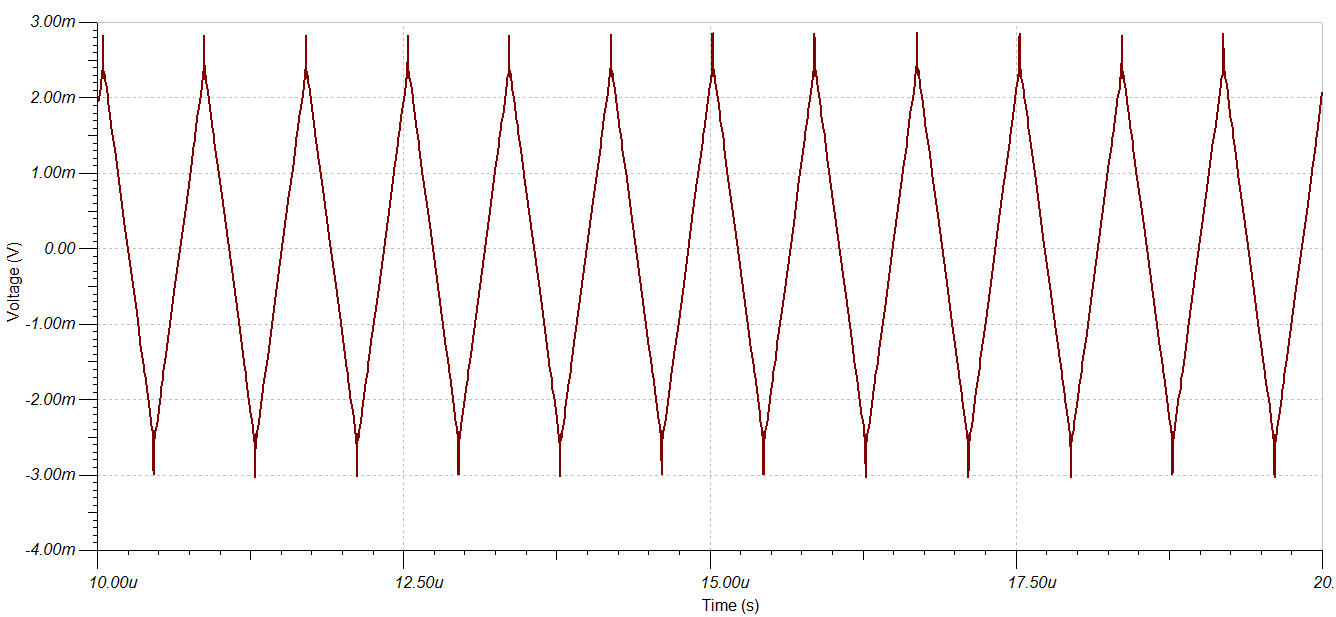
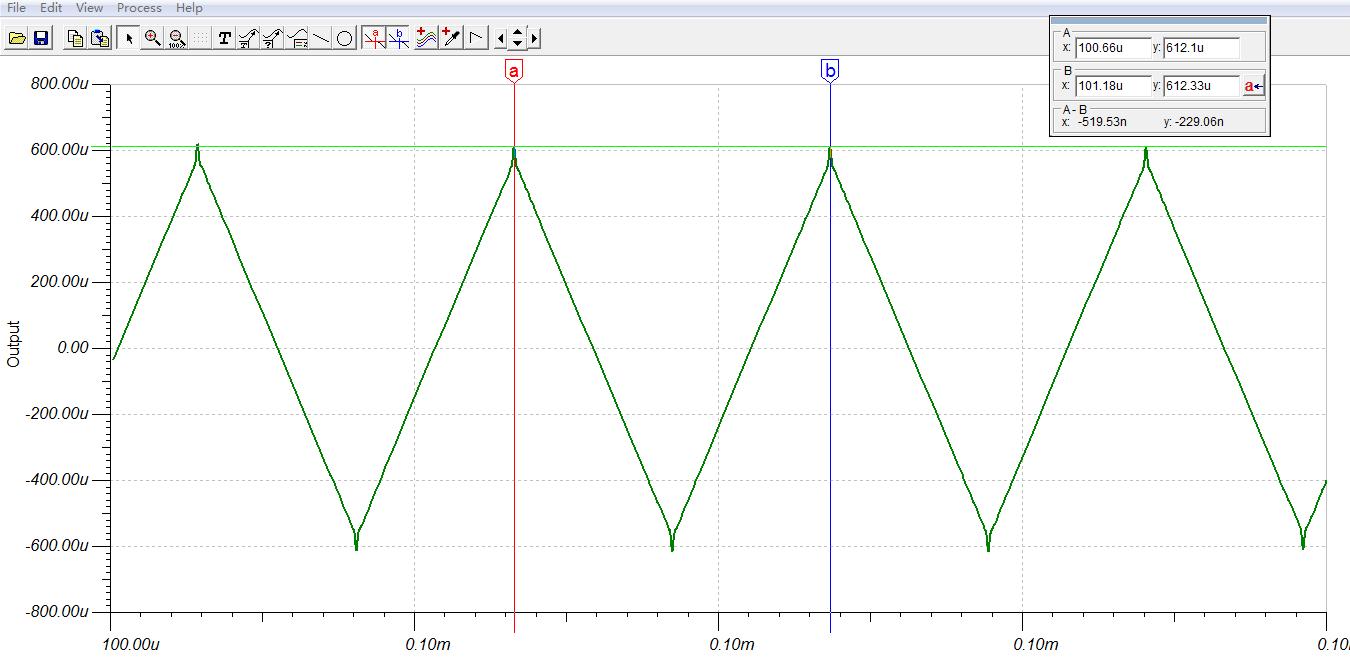
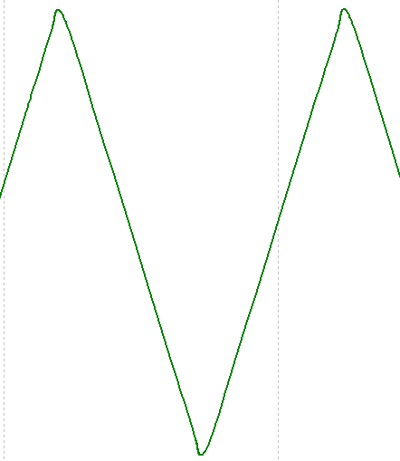
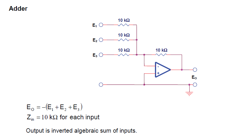
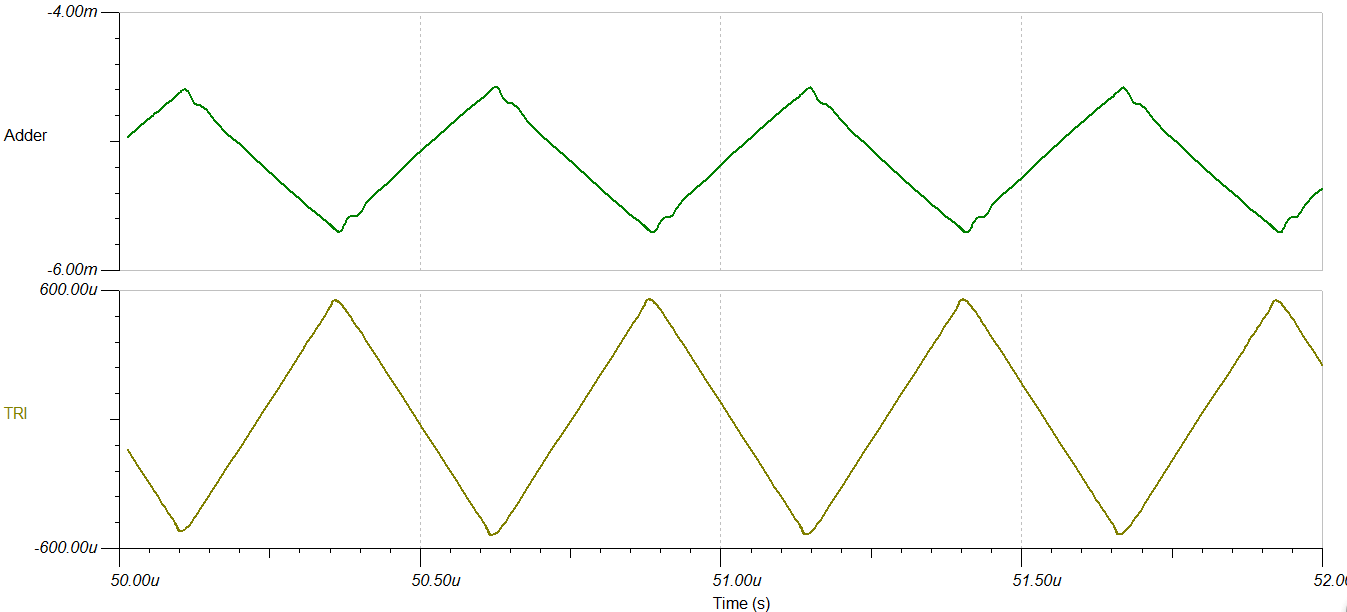
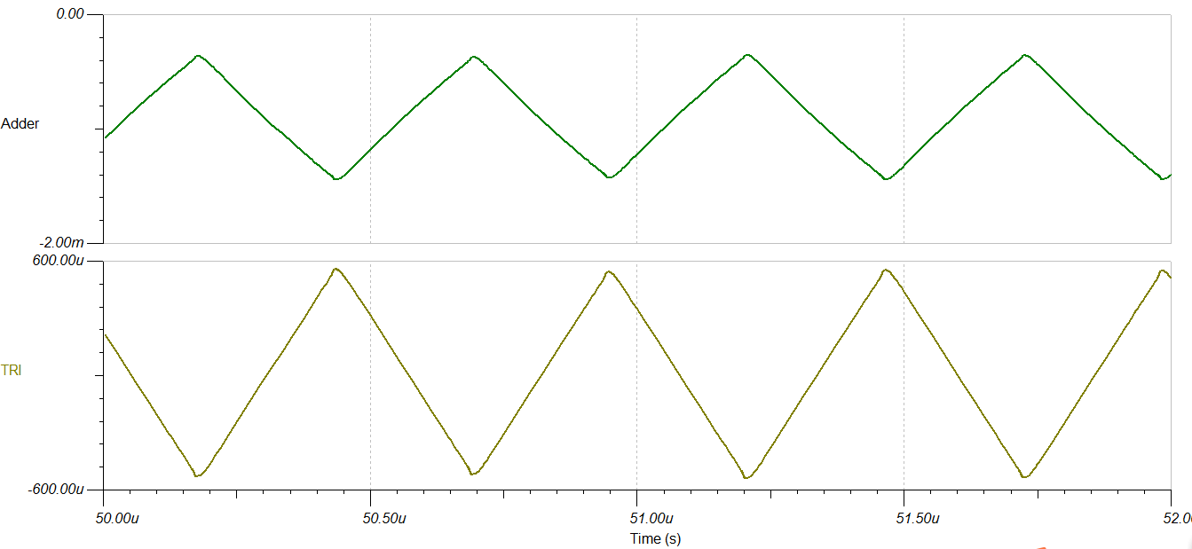
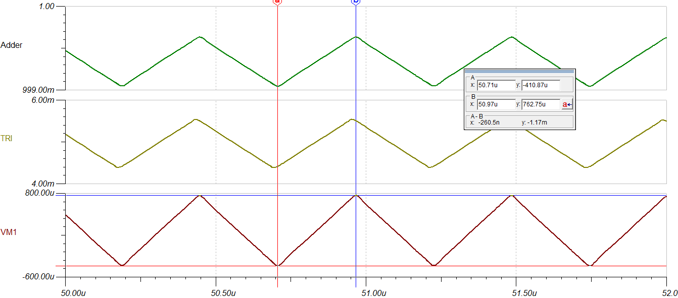
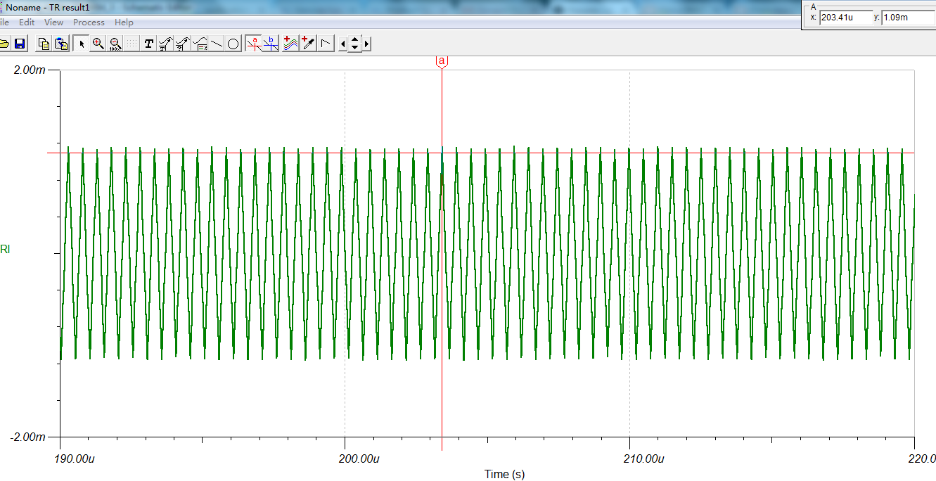
now i want to generate the 1MHz Triangular waveforms and i have seen an idee in the paper as follows. It consists of a comparator (A) and an integrator (B) as shown.
Because the frequency of my generated triangular waveform is 1MHz. I have seen the datasheet of LM741. But i also don't konw, whether i can use LM741 as coparator and integrator to generate this triangular waveform. If not, can you recommand me a useful IC or amplifier for my use?
Thank you so much for your help!
Best regards