This thread has been locked.

If you have a related question, please click the "Ask a related question" button in the top right corner. The newly created question will be automatically linked to this question.

CCS/AFE031: AFE031(DAC mode) no output

Part Number: AFE031
Other Parts Discussed in Thread: TMS320F28069,

Tool/software: Code Composer Studio

Dear colleagues,

I tried to use TMS320F28069 to control AFE031, in order to output the sine wave signal.

I used these modules of AFE031: SPI, DAC, PGA, FILTER and PA.

But I couldn't get any signal at the output of AFE031. 

When I send configuration commands to AFE031, I found that F28069 received the data returned by AFE031 from time to time, is this right?

I also tried to get the value of the registers in AFE031.

For example, I try to read the 0x02 register that by default is set to 0x32, if I send two 0x8200 instructions, should the returned data be 0x8232?

In addition, whether the DAC register of AFE031 can be read or not?

Could you help me find out if there are any problems with my configuration?

Here is the configuration code:

void HAL_afe031Init(void)
{
    HAL_afe031_cfgGpio();

    HAL_spi_fifoInit();
    HAL_spi_init();

    HAL_afe031_regWrite(HAL_AFE031_RESET_REG,0x14); //0001 0100
    DELAY_US(2);

    HAL_afe031_regWrite(HAL_AFE031_ENABLE2_REG, 0x06); //0000 0110
    DELAY_US(2000);

    HAL_afe031_regWrite(HAL_AFE031_CTRL_REG, 0x08); //0000 1000
    DELAY_US(2);

    HAL_afe031_regWrite(HAL_AFE031_CTRL2_REG, 0x00);
    DELAY_US(2);

    HAL_afe031_regWrite(HAL_AFE031_CTRL2_REG, 0x20); //0010 0000
    DELAY_US(2);

    HAL_afe031_regWrite(HAL_AFE031_ENABLE2_REG, 0x07); //0000 0111
    DELAY_US(2);

    HAL_afe031_regWrite(HAL_AFE031_GAINSEL_REG, 0x30); //0011 0000
    DELAY_US(2);

    HAL_afe031_regWrite(HAL_AFE031_ENABLE_REG, 0x03); //0000 0011
    DELAY_US(2);
    HAL_afe031_regWrite(HAL_AFE031_ENABLE2_REG, 0x0F); //0000 1111

    HAL_afe031_regWrite(HAL_AFE031_ENABLE_REG, 0x23); //0010 0011
    DELAY_US(2);

    SpiaRegs.SPICCR.bit.SPICHAR = 9;

    EALLOW;
    GpioDataRegs.GPADAT.bit.GPIO7 = 1;
    EDIS;
}

void HAL_afe031_cfgGpio(void)
{
    EALLOW;

    //SD PIN
	GpioCtrlRegs.GPAPUD.bit.GPIO12 = 1;		// Disable Pullup
	GpioCtrlRegs.GPAMUX1.bit.GPIO12 = 0; 	// General Purpose
	GpioCtrlRegs.GPADIR.bit.GPIO12 = 1;		// Output
    // SD=0
	GpioDataRegs.GPADAT.bit.GPIO12 = 0;		// 0

    //DAC Pin Enable
	GpioCtrlRegs.GPAPUD.bit.GPIO7 = 1;		// Disable Pullup
	GpioCtrlRegs.GPAMUX1.bit.GPIO7 = 0; 	// General Purpose
	GpioCtrlRegs.GPADIR.bit.GPIO7 = 1;		// Output
    // DAC=0
	GpioDataRegs.GPADAT.bit.GPIO7 = 0;		// 0

    // INT Pin
	GpioCtrlRegs.GPAPUD.bit.GPIO6 = 1;		// Disable Pullup
	GpioCtrlRegs.GPAMUX1.bit.GPIO6 = 0; 	// General Purpose
	GpioCtrlRegs.GPADIR.bit.GPIO6 = 1;		// Output


    EDIS;
}

void HAL_spi_fifoInit(void)
{
    //
    // Initialize SPI FIFO registers
    //
    SpiaRegs.SPIFFTX.all = 0xE040; //1110 0000 0100 0000
    SpiaRegs.SPIFFRX.all = 0x204F; //0010 0000 0100 1111
    SpiaRegs.SPIFFCT.all = 0x0;
}

void HAL_spi_init(void)
{
    SpiaRegs.SPICCR.all =0x000F;  //0000 0000 0000 1111
    SpiaRegs.SPICTL.all =0x0006;  //0000 0000 0000 0110

    SpiaRegs.SPIBRR = 1; //SPICLK = LSPCLK/4 = SYSCLK/4/4

    SpiaRegs.SPICCR.bit.SPISWRESET = 1; // Ready to transmit

    SpiaRegs.SPIPRI.bit.FREE = 1;  // Set so breakpoints don't disturb xmission
}

void HAL_afe031_regWrite(Uint16 addr, Uint16 data)
{
    addr = addr & 0x7F;

	cmd = (addr << 8) | (data & 0xFF);

    SpiaRegs.SPITXBUF = cmd;

    DELAY_US(1);
}

Best regards.

  • Hello Hao Li,

    I would like to first verify the hardware setup before going into software. Could you send a schematic of your hardware setup. Are you using a specific PLC kit?

    Best regards,

    Errol Leon
    Texas Instruments
    Precision Amplifier Applications Engineer
  • Hi Errol,

    Thank you for your reply!

    Yes, I used the TI PLC Development Kit, and I referenced the example program boostxl_afe031_f28379d_dacmode.

    Then I found the problem is that after every configuring to AFE031, enough delay need to be added to take effect: all DELAY_US(2) should be changed to DELAY_US(2000).

    Now I have three new questions:

    1. The DAC in AFE031 is a 10-bit DAC, is its acceptable input value between 0x0000 and 0x03ff ?

    I want to know the output voltage range of PA, and how will output voltage change when input value changes? 

    2. I tried to change the configuration of PGA in AFE031 from 1V/V to 0.5V/V, and I found the output voltage is reduced.

    Should PGA be a programmable gain amplifier, why the voltage will be reduced?

    3. In the example program, it used EPWM1 as the peripheral interrupt source of DMA and EPWM2 to generate interrupts.

    What are the benefits of using EPWM rather than CPU-TIMER?

    Best regards,

    Hao

  • Hello Hao,

    1.  Yes,  the DAC produces an acceptable output range of 0.1V to 3.2V (with VDVDD= 3.3V) for the PGA and PA in the signal chain of the AFE031.  The PA's output swing is dependent on the load.  For example, if the output current is ±300mA , the output swing would be 0.3V to 15.7V (with PA_Vs = 16V).   If the output current is ±1.5A , the output swing would be 1.3V to 14.3V (with PA_Vs = 16V). Attached below is a screen shot of the output swing limit located on page 5 of the datasheet.  

    The PA is configured with an inverting gain of 6.5V/V and is specified to operate from 7V to 24V and can deliver up to ±1.5A of continuous output current over the specified junction temperature range of -40°C to +125°C.

    2. Yes, the TxPGA on board the AFE031 allows the user the option to program the gain through the serial interface.  The Tx PGA gain settings are 0.25V/V, 0.5V/V, 0.707V/V, and 1V/V.

    3. Sending information in DAC mode example code is accomplished by one PWM source being used to set the DAC mode value to the correct value of the sine ramp that gets sent out.   The second PWM is used for bit rate to generate an interrupt and determine what frequency needs to be outputted.   I have attached a link below to an application note that describes this in more detail and its limitations (starts on page 16 of the application note).  

    Best regards,

    Errol Leon

    Texas Instruments

    Precision Amplifier Applications Engineer

  • Hi Errol,

    Thank you for your reply!

    My question relates to the following post, but I can't reach Jose.

    e2e.ti.com/.../365578

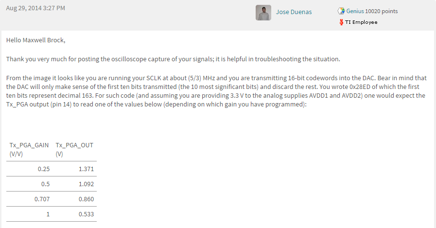
    1. He said DAC will only make sense of the first ten bits transmitted (the 10 most significant bits) and discard the rest. But in example program boostxl_afe031_f28379d_dacmode, the sinetable data is from 0x0000 to 0x0400. Whether the effective data written to DAC(SPISIMO) is from 0x0040 to 0x0FFC(left-aligned) or from 0x0000 to 0x03FF(right-aligned)? 

    And how to calculate result(0.533V) when the input data is 0x28ED(if providing 3.3 V to the analog supplies AVDD1 and AVDD2)?

    2. From the table in screenshot, the output of PGA will increase when the PGA gain decreases. But my measurement result is the opposite. When the PGA gain changed from 1V/V to 0.707V/V or lower, the output will also decrease.

    3.In addition, I think AFE031 should have a voltage bias after DAC. Where is it?

    Best regards,

    Hao 

  • Hello Hao,

    1. This is true that the DAC will only make sense of the first 10 bits starting from the most significant bit.  I will need to look into the the dacmode code to look at the sine table data. 

    2. The table posted on the thread is incorrect.  The output voltage  is  Vout=Gain*Vin .  As gain decreases the output should decrease.   

    3.  REF1 is the bias for the PA and REF2 is the bias for PGA's and 4th order low pass filter (LPF). 

    Best regards,

    Errol  Leon

    Texas Instruments

    Precision Amplifiers Application Engineer

  • Hi Errol,

    You are correct on the first question, I did not look carefully at the example program.

    I think this post has been solved.

    Thank you for your help!

    Best,

    Hao

  • Hello Hao,

    Glad I could help!

    Best regards,

    Errol