This thread has been locked.

If you have a related question, please click the "Ask a related question" button in the top right corner. The newly created question will be automatically linked to this question.

OPA2172: replace TL082 and has some issue

Part Number: OPA2172
Other Parts Discussed in Thread: TL082, , OPA2192, OPA192

Hi, my customer was using TL082 to do the output voltage and current sample of charging pile. It's LLC DC/DC converter with switching frequency ranging from 30k to 300k, the output voltage range is from 200V-750VDC and should be <0.5% error, the output current is 0-30A with <1% error.

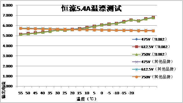
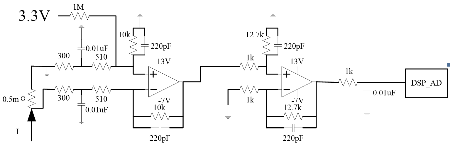
TL082 can pass the test at room temperature, but due to the large drift, it can not pass the test at high or low temperature. So they choose OPA2172 and OPA2192 to do the test for it's low offset drift, but it cannot pass the test even at normal temperature. The test schematic is as below, they only replace the amplifier from TL082 to OPA2172 or OPA2192.

voltage sample circuit

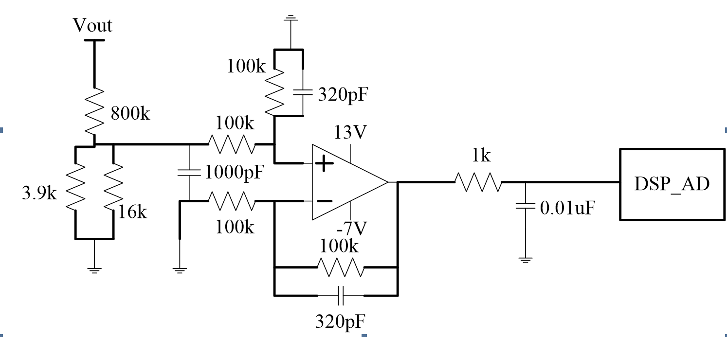
current sample circuit

They will test the charging pile under constant current mode or constant voltage mode.

They tested with OPA2172 at constant 5A output current mode, they tested with output voltage at 750V, 700V, 650V till 200V with electronic load. It fails at 200V output voltage, and the output current will have ripple and will be about 4.5V to 5.5V.

They tested with OPA2192 at constant output voltage mode. With output voltage higher than 700V, they increase the output load till 30A and everything is good. When set the output voltage reference to 650V, they increase the output load to 5A and the voltage cannot be kept stable, it will decrease to 350V and then increase to 650V, and kept swing between 350V to 650V.

1. Do you have any good recommendation to replace TL082 in such a situation with offset drift less than 4uV/C?

2. For OPA2172, the datasheet emphasize that it's single supply, but it also says that the supply range is: +4.5 V to +36 V, ±2.25 V to ±18 V, why? Is it okay to use OPA2172 with the supply shown in the picture above?

3. Are there any bad point with the supply shown in the picture above, V+ 13V, V- -7V, since they are not opposite.

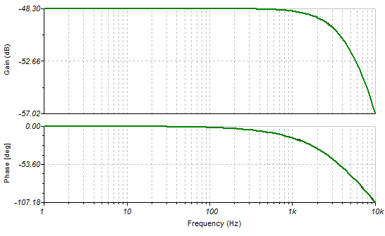
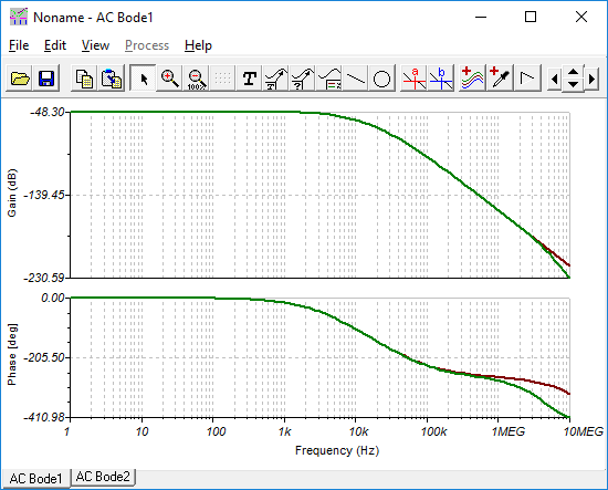
4. Any idea what would cause the system to be unstable with OPA2172 and OPA2192? The current and voltage are all DC component with switching frequency(30k to 300k) ripple.

  • Howard,

    1 The two alternatives you chose should be good replacements.
    2 Yes that is fine. The op amp doesn't know (or need to know) what ground voltage is
    3 Yes that is fine as long as input and output ranges are honored. They are in range.
    4 The frequency compensation and load provide good phase margin in simulation. I wouldn't expect an issue.

    May I assume that this sampling circuit is not part of the power supply voltage or current feedback (regulation) loop?
  • Hello Howard,

    Regarding the drift issue:

    What are the high and low temperatures? Is there any data available that provides a measure of what "can't pass" means?

    Something doesn't seem right about the drift results obtained with the different op amps. The typical drift is is 18 uV/°C for the TL082, 0.3 uV/°C for the OPA2172 and 0.2 uV/°C for the OPA2192. If the drift were completely attributible to the op amp, then we would expect the OPA2172 and OPA2192 to exhibit much better drift performance than the TL082, and not the other way around. 

    There are a lot of resistors in the circuits and there isn't any information about them execpt for their resistances. Resistors have a drift temperature coefficient (tempco) that is dependent on their design and materials. That tempco is specified in the electrical specifications for the resistor. If the dift of the TL082 happened to be the opposite of the resistors in some portion of the temperature range, there could be a cancellation effect resulting a lower net drift over that particular range. The OPA2172 and OPA2192 having very low drift might be dominated by the other circuit element drifts. This something to consider.

    By the way, do the op amps have power supply decoupling capacitors from their V+ and V- pins to ground? They should!

    Regards, Thomas

    Precision Amplifiers Applications Engineering


  • Of course it's not only related to drift.
    OPA2172 and OPA2192 behave worse at normal temperature, I think the reason is the control loop is changed(phase margin and gain margin of the whole current or voltage control system is changed). If we can tune the control loop well, it should behave good among different temperatures for its lower drift.
    1. I wonder what parameters of OPA will affect the loop.
    I will ask for more details of TL082 test result.
    The customer is really interested in the following questions:
    2. For OPA2172, the datasheet emphasize that it's single supply, but it also says that the supply range is: +4.5 V to +36 V, ±2.25 V to ±18 V, why?
    3. Are there any bad point with the supply shown in the picture above, V+ 13V, V- -7V, since they are not opposite.
  • Hi Howard,

    1. I wonder what parameters of OPA will affect the loop. I will ask for more details of TL082 test result.

    There is some question if the 1 k series isolation resistor is sufficiently high enough to isolate the op amp output from the 10 nF load. I suspect so, but it would be best to observe the op amp output across temperature looking for any presence of oscillation. If the op amp breaks into oscillation the dc performance, which includes voltage offset drift, will be badly affected by the oscillation.


    The customer is really interested in the following questions:


    2. For OPA2172, the datasheet emphasize that it's single supply, but it also says that the supply range is: +4.5 V to +36 V, ±2.25 V to ±18 V, why?

    Op amp single supply operation capability is often desired as it is more easily accomplished compared to having to provide a dual (+/-) supply to power the op amp. Therefore, that desirable capability will be emphasized in the datasheet. The OPA2172 may just as easily be operated with dual supplies, but then dual supplies which results in higher cost is required.

    The OPA2172 Electrical Specification table is written for Vs = +/-2.25 V to +/-18 V operating conditions. If we go with a single positive supply the -Vs moves up from the negative voltage to zero volts, and +Vs moves up to a positive range of +4.5 V to + 36 V. Nothing changes in terms of the common-mode voltage range VCM, and the output voltage swing ranges; they are still specified and with respect to the -Vs and +Vs levels. The op amp provides the same levels of dc, ac and noise performance in either power supply arrangement.


    3. Are there any bad point with the supply shown in the picture above, V+ 13V, V- -7V, since they are not opposite.

    The OPA2172 may be operated with assymetrical power supplies without performance degaradtion. Again, the operating input and output ranges are with respect to the +Vs and -Vs levels. Just make sure that the VCM stays at least 2 V below +Vs, no matter what voltage +Vs is set to. If that were to happen the overall performance of the op amp would be degraded.

    Regards, Thomas

    Precision Amplifiers Applications Engineering

  • Howard,

    Simulation show no meaningful difference. Voltage feedback OPA192 vs. TL082

    Tina file: OPA192.TSC

    AC transfer function. (two different end sweep frequency)

  • Thank you. So I suggest that we can remove the "single supply" at the title of the datasheet. OPA2192 does not emphasize single supply.

  • This is the test result of constant 5.4A output at different temperature. The green one is TL082, and the orange one is non TI amplifier(same board).

    And by oscillation do you mean we have to monitor the output of TL082 throughout the temperature range? But the whole system with TL082 is stable, can I say that there is no oscillation?

  • Howard,

    Typical drift for TL082 is 18uV/C. The chart shows about 90C change. So typical VIO change is 0.018mV * 90C = 1.62mV

    1.62mV change on the 0.5 milliohm sense resistor is 3.24 Amps. 

    The drift observed is about 1.8 amps , so the actual TL082 drift is just over 1/2 of typical data sheet drift.