This thread has been locked.

If you have a related question, please click the "Ask a related question" button in the top right corner. The newly created question will be automatically linked to this question.

Comparator / 0V detection

Other Parts Discussed in Thread: LP211, TL331, LM397, LM393, LM339

Hi,

I want to do a zero detection on the main voltage (in France, 230Vac and 50Hz). Before doing it in real, I try to do it with simulation.
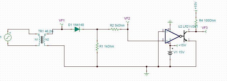
This is my design:

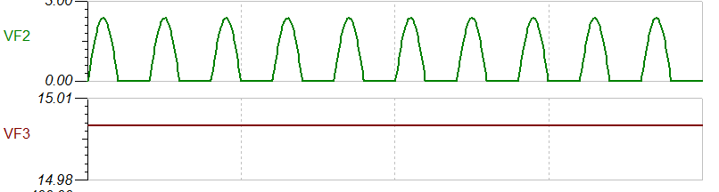
VF2 is ok, but VF3 is not.
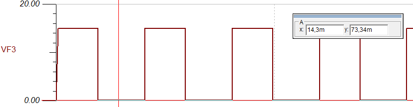
On the output (VF3), I want this signal :

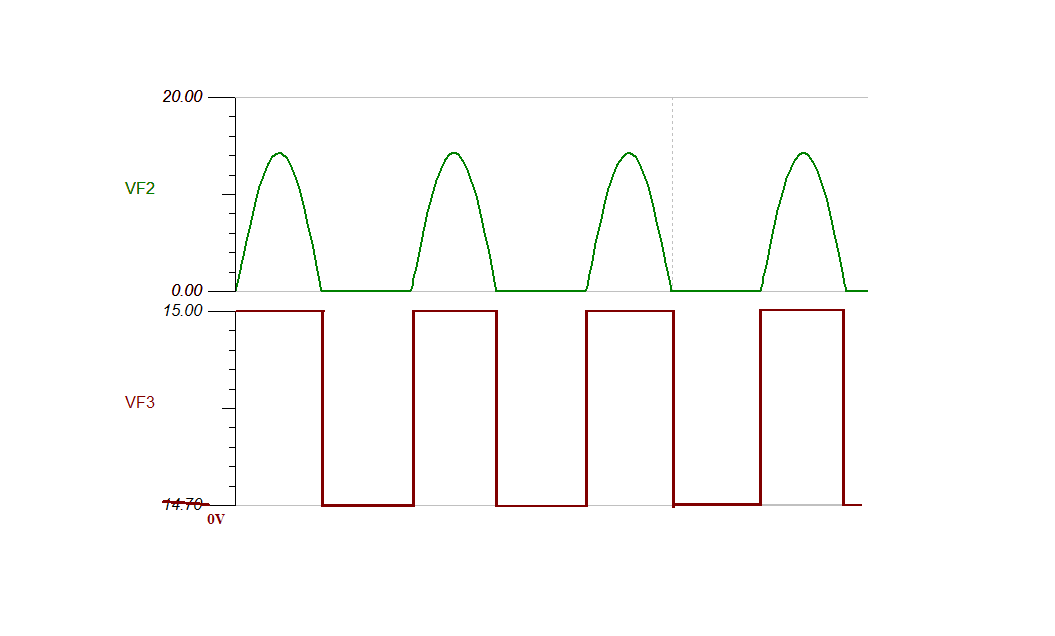
How must I do?Change the comparator? The design?
Thing that I can't change is only TR1. And my power supply is 15V. On the output, maximum level is +15V.
I don't need a lot of current on the output, 10mA is enough.

Thanks for your help.

Regards,

Florian

  • Hello Florian,

    The LP211 is a low power device, and cannot drive 10mA. 15V/100ohm = 150mA - WAAAYYY too much current - well above the specified 25mA drive.

    Also, the input range does not include "ground". The minimum input voltage is from 0.5V above V- to 1.5V below V+. So you may get improper outputs with the "real' device.

    I would recommend using the TL331 or LM397 (LM393 family), as these are ground-sensing inputs, less complicated and more suited for the application.

    You may also want to add some attenuation since it may be possible to have more than 15V on the input due to transients or noise (add a resistor from +IN to GND).

  • Hello Paul,

    I've tried to import TL331 and LM393 in Tina to do a quick simulation before testing it in real, but I didn't succeed. Can you help me please?

    Thank you.

  • Hello Florian,

    There is an extra ampersand (&) in the fist line in the .lib file.

    Delete the ampersand and it should work.

    I will alert the model folks to fix the ZIP file.

  • Hi,

    And what about the LM393 and 397?

    One of them hasn't got model and the size of the other is 0kb.

    Regards

  • Hello Florian,

    The "0kB" LM393 model is less than 1kb, so it is rounded to zero. It is a very simple model of only a few lines.

    The filename is LM393.5_1 after unzipping. The 5_1 extension signifies that it models the 5V specifications. You can change the "5_1" extension to .MOD or .CIR so that the TINA macro wizard can see it.
  • Hi,

    I succeed to import TL331 and LM393.

    "You may also want to add some attenuation since it may be possible to have more than 15V on the input due to transients or noise (add a resistor from +IN to GND)."

    I already add an attenuation with the 2 resistors R2 and R3, no?

    I don't know if my macros works, but I've very strange results with my simulation.

    LM393 :

    TL331 : 

    Regards,

    Florian

  • Hi,

    I succeed to have the good signal on the output, but it's not perfect.

    When I connect the inverting input on the ground, the detection is not ok, and on the output I have this signal :

    When I put a little signal on the inverting input (150mV), I have this signal :

    So on my output, I've never 0V, the low level is 73,35mV. How can I have 0V?

    Regards,

  • Hello Florian,

    I duplicated your results.

    Not sure what is going on with the TL331 model - I have to dig deeper into that one. One thing to note is that the TL331 model has sub-circuits, so you want to make sure the full model got imported - not just the first section.

    The LM339/393 model is a very simple transistor level model - much simpler that the actual "simple" LM339/393!

    I found I had to add a minimum of 100uV to the inverting input will get the output to "square up" the output. This seems to be a model artifact and, again..I have to look into this. For now, just add 100uV to the inverting input to square-up the output.

    The TL331 is the single version of the LM393/LM339, so you can use the LM393 model.

    However, since you have over 1V of differential overdrive voltage, the output of the actual device should be "square".
  • Hello Paul,

    I did the test with the LM393AP ; this is my results (yellow curve is the input, blue curve the output) :

    My inverting input is connecting to the ground. 
    I haven't exactly 0V on the output, but a little offset (about 60mV). How can I suppress it?

    Regards,

    Florian 

  • Hello Florian,

    The output will NEVER get to 0.00V. All output stages have a "saturation voltage" of the output device, which limits the lower output swing to the rail.

    This is shown in Figure 3 "Output Saturation Voltage" on page 10 of the LM393 datasheet.

    With a 10K pullup to 15V, this is a 1.5mA load current when low. According to the Fig 3 graph, the output should swing about 70mV from the negative rail with a 1.5mA load.

    You can try to reduce the load to allow the output to swing closer to the rail, but it will never hit the rail. The graph cuts off before the "plateau" where the output hits the minimum output swing at the lightest load. The graphs shows a minimum of 3mV with a load current of 10uA.

    So you can increase the size of the pull-up resistor to 100k (150uA at 15mV), or even 1Meg (15uA at 3.5mV), but this will slow the rising edge since load capacitance will create a RC time constant with the larger resistance.