This thread has been locked.

If you have a related question, please click the "Ask a related question" button in the top right corner. The newly created question will be automatically linked to this question.

Problems with LM358AM

Other Parts Discussed in Thread: LM358

Hello,

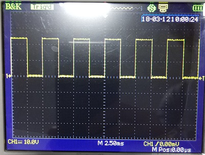
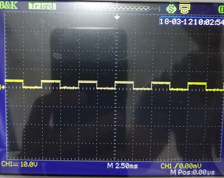
I use the LM358AM to measure RPM in a vehicle. I change the LM358AM to LM-358 and LM-358E. This new amplifiers burnt and stop work.
What´s the difference between this part numbers? Have some significative information thtat i didin´t seen?

Thanks and best regards

  • Rodolfo,

    I know the LM358AM part number, however LM358 without any suffix or just an "E" suffix is unknown to me. Can you check the new part numbers?

    At what step (for example initial board level test, system test , field failure) did the new LM358 fail?
    What is the failure rate and sample size, for example 20/1000 fail.
  • Hello,

    The components that I used are serigraph with Lm358AM, LM358 and LM358E.

    The problem is in input., causing problems in the vehicle panel.

    on the oscilloscope, showed an offset in the signal.

  • Rodolfo,

    The top waveform seems to be OK. I would expect a continuous pulse stream for an RPM application.
    The bottom wave does have offset, however the occasional missing pulses and distortion looks bad.

    I suggest to keep using LM358AM
  • Ronald,

    Could you explain the difference between LM358AM to others LM358 versions?


    Thanks
  • Rodolfo,

    I will answer on Monday. Thank for your patience.
  • Rodolfo,

    LM358AM was designed by National Semiconductor and acquired by Texas Instruments. LM358AD is designed by Texas instruments. There are also many other manufacturers that make LM358 in the same base name or similar names. Almost all of these LM358 versions are designed to have the same performance and have the same basic schematic. None of them are exactly the same.
  • Hi Rodolfo,

    can you show us a schematic?

    Kai
  • Hi Kai,

    Attached the schematic

    The rpm signal enters on SENSOR_DE_PULSO_1_IN and the output is on SENSOR_PULSO_1

    Thanks and best regards

  • Hi Rodolfo,

    to me it looks like a damaged input of LM358, because the - input (pin 2) has seen a negative voltage!

    Is the cap C99 present? Take care, behind this cap you would have a AC voltage which swings arround 0V. So, the - input of LM358 would see negative voltages all the time and if the input current exceeds 50mA the input is in danger to become destroyed.

    Could you at least insert a current limiting resistor in front of - input? But a much better idea would be to provide a posivitive bias, by the help of a voltage divider. e.g. No negative voltages should reach the - input, because even with current limitng resistor the performance of the second channel in the LM358 could be degraded.

    Kai
  • Hi Kai,

    Sorry, I forgot to mention, the CAP C99 and C100 is mount with 0R resistor and the R238 and R241 is not mount

    Thanks and best regards
  • Ok. Can you tell more about the sonsor? What output signal does it create? Is it like the upper line of your scope plot?

    Kai
  • Attached the examples os the signals

    Input - RPM of  vehicle

    output, the signal go to a port of a microprocessor

  • Is the sensor producing 24Vp?? What supply voltage do you use for the LM358?

    Kai
  • Yes,
    The supply voltage is the baterry of the vehicle.
  • Hi Rodolfo,

    I'm a bit confused. You say that the vehicle's power supply is 24V. And you show in the last scope plot a sensor signal which swings from 0V to 24V. Then you say, that the LM358 is also powered by 24V and that C99 is bridged and R238 is omitted. But why does the sensor signal in your first scope plot swing only between 0V and 12V? And why does the sensor signal in the second scope plot not swing down to 0V? Is it a measuring mistake of your "serigraph"? What would a proper scope show?

    In your first post you wrote that the LM358 "burnt and stop to work". As you said that you power the LM358 by the vehicle's power supply, are you aware that the vehicle's power supply can be extremely contaminated with glitches and overvoltage spikes? Do you protect the LM358 against these overvoltage spikes? Could it be, that the LM358 were damaged by these overvoltage spikes?

    Kai
  • Hi Kai,

    The first images and the last images are different situations.
    The first image is a test in a vehicle with baterry 12V.
    The last images are test in laboratory, with a frequency generator and voltage 24V.
    Test in a vehicle show before and after LM358 burn and stop work. The signal is the input of the CI. The output don´t work after burn.
    When the component is with problem, the offset of the signal make a short circuit in the panel o fthe vehicle.
    I´m aware that the vehicle's power supply can be extremely contaminated with glitches and overvoltage spikes, but the circuit is used with a large quantity of vehicles and never had this problem.
    To a future update of circuit, What do you suggest?
    What I think strange because always used LM358AM, for years it was used this CI.
    When we use LM358, happened this problem.
    Can you exert any correlation?

  • Hi Rodolfo,

    I would power the LM358 with a much lower supply voltage. Why not using a well regulated and well protected supply voltage? I would never power the LM358 directly with the vehicel's power supply. This voltage is from hell, can show extreme overvoltage spikes, negative voltages, etc. Then I would use a voltage divider for the sensor signal containing protecting and filtering elements, guaranteeing that the LM358 inputs are never stressed.

    That the problem occured when switching from the LM358AM to the LM358 is pure coincidence to me.

    Kai
  • Hi Kai,

    It´s a possible be a coincidence, but when I use the LM358AM in the same vehicles that I had the problem, the CI didn´t burn. When I put the LM358 sometimes the problem occur again

  • Hi Rodolfo,

    ok, if you suspect the LM358 then take again the LM358AM. Could it be that the LM358 is a trashy version from a "no name" manufacturer? Such a device could differ in the specifications. Do you know the manufacturer?

    Nevertheless, I would think about a design change. You need to protect the inputs from negative glitches and overvoltage spikes and you need to limit the supply voltage to sane values.

    What sensor do you use?

    Kai