This thread has been locked.

If you have a related question, please click the "Ask a related question" button in the top right corner. The newly created question will be automatically linked to this question.

TLV3404: Piezo element // 2 stage op-amp design

Part Number: TLV3404
Other Parts Discussed in Thread: TDC1000, TLV9002, OPA348, TLV3012, TLV8811, TLV8802, LM6134, TLC272

Hi,

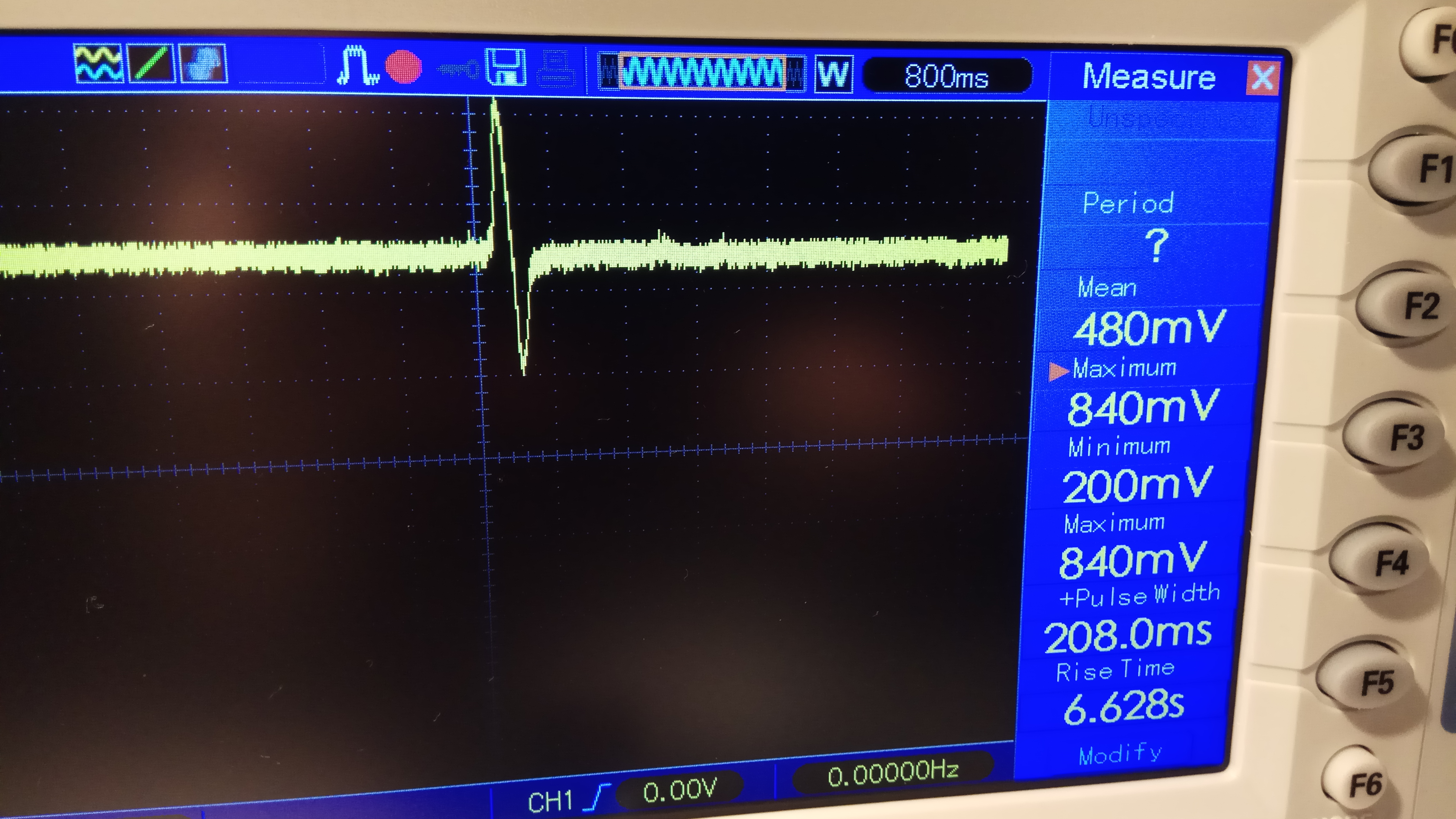
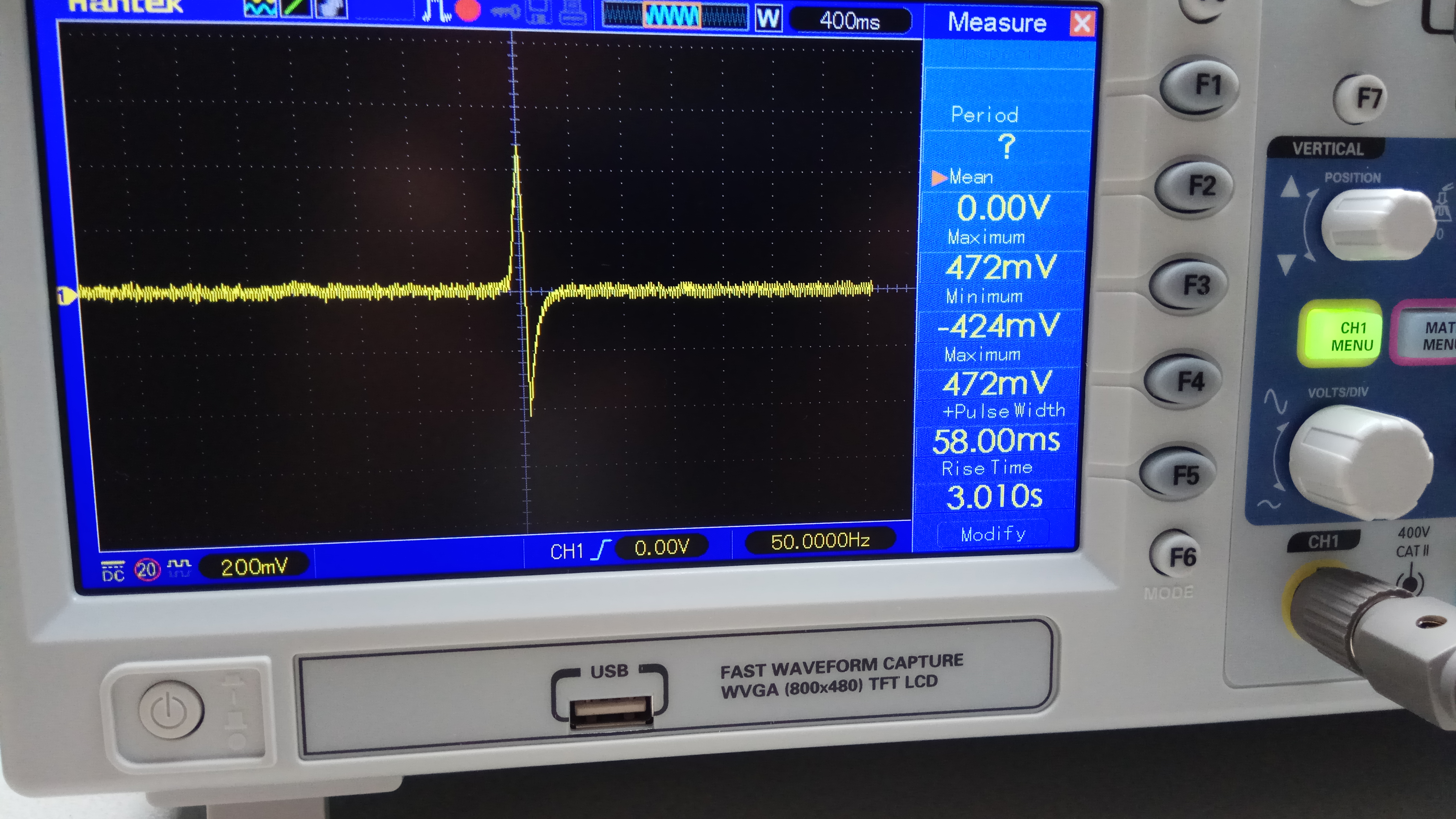
We are working an a design with a piezo element. This piezo element (long cable) generate an output when it is triggered (e.g. by a car driving over it). The piezo output has to be digitalized such that it can server as an interrupt to a processor. For this I want to use 2 opamps.

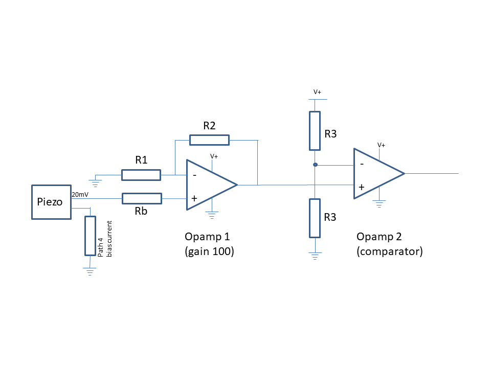
The first opamp amplifies the piezo signal and the second opamp is a comparator. The output of the 2nd opamp is fed into a processor. For the opamp design the following is considered

  • Piezo Sensor cable:
    • Ouput varies between 20 and 50 mVs
  • Opamp low power - TLV3404 (low power opamp is key as it should be possible to run on a battery)

As the piezo cable is a separate sensor I am not sure how the input bias current path could run. Have a quick sketch drawn below. As I am not an opamp designer I hope you can give me some guidance or tips how I could make this design work

Thanks a lot!

  • Hi Jeroen,

    have you a link to the datasheet of piezo cable?

    I would still add a protection and filtering scheme to the input of first OPAmp.

    By the way, the TLV3404 is a quad comparator. It's not an OPAamp.

    Kai
  • Hi Jeroen,

    It would be helpful if you could provide a bit more information on your design goals. For example:
    * How much power consumption is acceptable?
    * Does the piezo output between 20mV and 50mV max, or is that the range all signals exist in (basically all signals are baised to 35mV)?
    * What type of output signal do you expect from the piezo? Pulses, sine wave, etc.
    * What is your threshold voltage for the comparator stage?

    A gain of 100 might work depending on your supply voltages (assuming low because of battery power), but if you amplify 50mV by 100, you'll hit the rails on the output. I would recommend shooting for an amplification between 20 and 40, which will give you a more reasonable output voltage range without hitting the non-linear regions of the amplifier.

    If you can provide some more details, we should be able to help you with your design a bit further.
    -Paul
  • Jeroen

    from my ultrasound days, we developed a product called the TDC1000.  since this product was used for multiple applications, it contains the ability to excite the piezo sensor and receive a signal back.  It sounds like you are using the piezo in microphone mode only, and will not be exciting it.  If that is the case, only the receive portion of the product will be relevant.  the tlv3404 is a quad comparator, so that alone will not satisfy your requirements.  Please clarify for those monitoring this post if their is any excitation being applied to the piezo sensor and what supply voltage is available.

    Chuck

  • Hi Kai, Paul, Chuck,

    Thanks a lot for your feedback - below some additional info:

    @Kai – comparator vs OPA. As said I am not an opamp expert but for this scenario could I not use the TLV3404 as both comparator and OPA? (afaik they are optimized differently (??))

    • Power consumption for opamp design– max in range of uA when “monitoring” the piezo sensor
    • My processor sleeps at approx. 1uA. System going in mA range for power consumption is a no go when powered by batteries
    • Battery powered – voltage 3.6V
    • Comparator threshold - 2V (but we could lower it when a smaller gain is used). Piezo input above 20mV should trigger comparator

    @Paul – maybe a gain of 20 – 40 makes more sense (and make comparator threshold lower)

    Jeroen

  • Hi Jeroen,

    I would recommend taking a look at a device like the TLV9002 for your application. It has a fairly low power consumption and the bandwidth should be sufficient for the pulse duration that the piezo will produce.

    It is also a good idea to set your comparator threshold lower (maybe around 0.5 or 0.7V) because you're using a single supply and 2V is above mid supply which could be difficult to make work with a ground referenced signal. Your choice of threshold should also be based on system noise, so if you have a very noisy input signal, then you may want to raise it some more.

    Also, it is not recommended to use a comparator as an amplifier. They are optimized differently and you won't get the behavior you desire.

    I've attached a TINA schematic for you to take a look at which uses a gain of 40. Both a 20mV signal and a 50mV signal exceed 750mV and the pulse I provided was a pretty fast pulse. Longer pulses will improve the performance of the system.

    Best,

    Paul

    TLV9002_Piezo.TSC

  • Hi Jeroen,

    based on the piezo signal modelled by Paul if have created and simulated the following circuit:

    It uses another OPAmp, the OPA348. As comparator the TLV3012 was chosen, because it contains a stable voltage reference, which might be useful for setting the comparator threshold in a battery powered application. The circuit is optimized for very low supply current. The gain of the OPAmp (factor 40) is adopted from Paul's simulation.

    There's a 1M resistor at the input of circuit to provide a current path to GND for the input bias current of OPAmp. Two antiparallel diodes serve as input protection. R9 limits the input current in an overvoltage event. C2 is added for stability. It provides a phase lead compensation and restores the phase margin. The TLV3012 generates a stable voltage reference of 1.242V. A high ohmic voltage divider is used to create a threshold voltage of about 0.62V, which is in the range between 0.5V and 0.7V, as recommended by Paul. C1 is used to stabilize the threshold voltage.  

    Kai

  • Hi Kai, Paul,

    I am impressed with the design suggestions // seems like a good solution. Have some questions about it:

    1. Total power consumption is around 50(uA).
      1. This is ok but more than I have in mind (would like to go below 10 uA)
      2. Therefore I am wondering if it would be possible (or not) to use other nano-power op-amps like the TLV8811, TLV8802, TLV340, TLV 8541 etc. (in combination with a comparator like the TLV3012 or the  TLV340x)

    2. I always see op-amp gains with different values (small (kOhm) or large (MOhm)).
      1. Do you know what the design criteria is in such a low power op-amp design or what it is in general?

    @Kai - would it be possible to send me the TINA file?

    Let's see if we can get this design working (will keep you up 2 date).

    Thanks,

    Jeroen

  • Hi Jeroen,

    I think you've got a good start as far as the circuit goes. Swapping in a lower power device should be okay, just be aware that you will probably trade off some bandwidth and you'll have see what type of bandwidth your circuit will need once you have a clearer sense of the type of input signals. I've alerted the low-power amps team, hopefully they can chime in and provide some guidance as well.

    For your second question, I'm not quite following what you're asking. The order of magnitude for resistors around a device can impact current consumption, stability, and the impact of non-ideal op-amp properties like input bias current. Typically for feedback resistors, kOhm is the right type of size range to balance those types of concerns. I recommend taking a look at TI Precision labs, section 2 (training.ti.com/ti-precision-labs-op-amps-vos-and-ib for a good starting point on some of the non-ideal properties of op-amps. The rest of the series has excellent content which can help you understand bandwidth (section 5) and stability (section 10).

    Best,
    Paul
  • Hi Jeroen,

    first, when I looked at the scheme Paul was proposing, I thought to me that one should be a able to use an OPAmp offering a much lower supply currrent. But I was wrong! If you take such an ultra low power OPAmp you will not get the unity gain bandwidth and slewing rate necessary to handle the piezo signals. A unity gain bandwidth of at least 1MHz seems to be mandatory. So, the only OPAmp which was as fast as Paul's TLV9002 and was drawing a bit less supply current at the same time was the OPA348. So, I totally agree with Paul.

    You see that I have used rather high resistance values to be able to save supply current. But an additional increase would not help much, because the most supply current is drawn by the idle current of OPA348. The consequence of using high feedback resistances is that you must do something to improve the stability again. That's why C1 and C2 are needed. In a design with much lower feedback resistances these caps could be omitted.

    jeroen_piezo.TSC

    Kai

  • Hi Kai, Paul,

    Thanks for the suggestions and tips. For now all my questions are answered and I will build the design during the weekend.
    I do appreciate all your effort - keep up this good work! Let you know when it works :-)

    Jeroen
  • If I got a pulse of 4uS at the piezo ,the bandwidth will be enough ?
  • In this case, the input signal is small signal (~20mV) so you're limited by the bandwidth of the part. 4us is going to be too quick for a 1MHz device, 10MHz and above will be a better choice. A pulse needs at least the 3rd harmonic and having the 5th would be better. This means that 4us is 250kHz with harmonics at 750kHz and 1.25MHz, and with a high gain (~40) as has been shown in previous posts, you can see the need for higher GBW products.

    -Paul
  • Hi John,

    are you Jeroen?

    Kai
  • no im not Jeroen and thanks for the fast answer Paul
  • Hi Kai, Paul,

    Before I create a test PCB, I have build a test setup on a breadboard.

    To test the first stage op-amp and to check the piezo signal I used an LM6134 (had nothing available in DIP package)

    Two things which I noticed on the scoop (see below)

    1> The piezo signal seems to be stronger when pressed and more symmetrical, so in the end I might want to use a smaller gain

    2> Feeding the piezo input to the LM6134 (PIN3) with gain of 10 (100k / 10k) and VCC 3.6(V) -->  I have an offset of around 480 (mV)

    So maybe you have some ideas where the 480(mV) comes from and what is the best way to get ride of this?

    Rgds, Jeroen (not John :-))

     :

  • Can you measure the output signal of the piezo directly (ie before the amp chain)? How much DC offset is there present at the input of the op-amp? The LM6134 has max offset of 2mV so I would only expect about 20mV of DC offset due to the op-amp itself.

    -Paul

  • Hi Jeroen,

    the LM6134 is no CMOS OPAmp but has bipolar transistors in the input stage which results in a strong input bias current. This input bias current generates a big voltage drop across the 1M resistor in parallel to the piezo.

    Kai
  • Hi Paul, Kai,

    The offset when only measuring the piezo is 0(mV) - see picture below. So the offset somehow (imho) comes from the LM6134.

    Kai, you mentioned that the used op-amp generates too much input bias current (datasheet says 'typical 110(nA)' - and over 1M resistor this is 110(mV)) which indeed is what I see (in the above 480(mV) a larger resistor was used).

    Do you have a suggestion which op-amp I could use to test the circuit as a whole (for breadboard testing DIP package only / no SMD pls :-))

    Jeroen

  • Hi Jeroen,

    why not taking the OPA348? The TLC272 should also work for a first testing. This is a CMOS OPAmp with low input bias current, too.

    Kai
  • Hi Kai,

    Not using the OPA348 for the simple reason that it does not come in a DIP package. I am only used to work with breadboard before creating a PCB protoboard.

    (maybe silly question but are there other ways to test non-DIP packages?)

    The TLC272 comes in a PDIP package so that is one I can use to test.

    Thanks

    Jeroen

  • Hi Jeroen,

    to use SMD parts on a breadboard solder very very thin copper wires directly to the SMD pins. Use lots of flux, turn down the temperature of soldering iron to 300°C and touch the SMD pins with the iron only for a very short time. Then solder the other ends of these very very thin wires directly to the resistor wires and capacitor wires the SMD pins shall be connected to.

    There are also adapter boards available which carry the SMD part and lead the SMD signals to solder terminals:

    www.breadboard-adapters.com/.../SOIC8-adapter.html

    Kai
  • I think I prefer the adapter boards // just ordered a bunch of them. thanks for this info.
  • Received the adapters and got the circuit working with the OPA348 and the TLV3012. The detection of the piezo signal goes very well.Have connected the output directly to a micro processor and signal is received.

    However there is one issue which I have not found a solution for. After measuring on the oscilloscoop I found out that when the output (comparator) goes from LOW to HIGH the first 50 usecs the signal bounces a couple of times.Not sure what the best measurements are to eliminate this?

  • Hi Jeroen,

    you could add some hysteresis:

    Kai

  • Thanks Kai, that did the job! No more swing in the output