This thread has been locked.

If you have a related question, please click the "Ask a related question" button in the top right corner. The newly created question will be automatically linked to this question.

TLC2264: TLC2264 getting damaged repeatedly, could it be an ESD issue?

Part Number: TLC2264
Other Parts Discussed in Thread: STRIKE, TLC272, TLC277, TPD2E007

Hello,

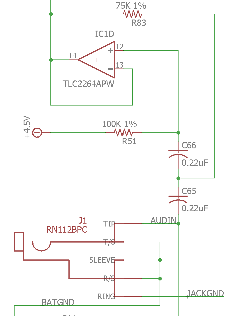
I'm having a problem where a TLC2264APW chip is repeatedly getting damaged in my circuit.  One op amp in the quad package is connected as a Sallen-Key high-pass filter with cutoff around 10Hz.  The portion of the circuit touching my input looks like this:

The symptom is that the op amp ends up drawing way more current than it should (>100mA).  Fortunately it's powered from a voltage regulator with current limit and it brings the whole supply down without causing more damage.  However, the TLC2264 package in question gets very hot to the touch, which proves to me that it is the source of the problem.

My worry is that an instrument cable can be plugged directly into the 1/4" instrument jack -- then the tip connection of the cable will be capacitively coupled (via those two 0.22uF caps in series) directly to the op amp input.  Is it possible that ESD events on the cable tip (when a person touches the tip for example) could zap the TLC2264, causing the symptoms I've quoted above?  Is there anything I can measure to determine if indeed the damage is caused by an ESD event?

Finally, if the failures are indeed caused by ESD can you recommend a solution to prevent them in the future?

Thanks!

-Brian Kaczynski

  • Hi Brian,

    what you experience looks like latch-up. A latch-up can occur if a too high current flows into the input or ouptut of TLC2264. Because of that the input current should be limited to under 5mA which can simply be done be a current limiting resistor in series to the input pin of TLC2264.

    Kai
  • Hi Brian,

    It sounds like they are, but can you confirm that the devices permanently damaged? Or does power-cycling the devices return them to normal operation?

    Either way, you're correct that without any protection on the IN+ pin the circuit is open to possible ESD strike damage.  Have you considered adding an external ESD protection diode between the audio input and GND to clamp any ESD strikes to a lower voltage?  Another suggestion would be to add a 10k resistor between C66 and IN+ of the amp.  It shouldn't cause any differences in the circuit operation but will help limit any current into the internal structures in the op amp if/when voltages above the supply voltage reach the amp.


  • Hello Collin,

    Yes, I can confirm that the damage seems to be permanent. Power cycling the system doesn't fix the problem. That is why I suspect ESD damage rather than latch-up.

    The 10k series resistor can be added in a future revision of the product but unfortunately we have a production batch of assembled units and some of them exhibit this problem whereas others do not. We're a bit scared that the products might fail in the field if it's an ESD issue.

    Thanks for your input!
    -Brian
  • Hi Brian,

    I would try this scheme here:

    The two BAV99 diodes clamp the overvoltage to the supply rails. This allows to keep R4 small. To limit the current through theses protection diodes there's another 470R resistor at the input of circuit. I also added a low pass filtering cap C3. This can absorb ESD as well, if the voltage rating is chosen properly.

    Kai

  • Thanks Kai. At this point I'm looking for the simplest (minimum component) fix that will resolve the problem. I have no problem inserting a 10k resistor in series with the op amp input if that will fix the problem. It's a bit disappointing that the op amp isn't internally protected enough but I guess we will have to live with that...
  • Hi Brian,

    that problem do you have with any other CMOS-OPAmp as well and from any other manufacturer.

    The datasheet of TLC272 contains a useful information:

    "Because CMOS devices are susceptible to latch-up due to their inherent parasitic thyristors, the TLC272 and
    TLC277 inputs and outputs were designed to withstand –100-mA surge currents without sustaining latch-up;
    however, techniques should be used to reduce the chance of latch-up whenever possible. Internal protection
    diodes should not, by design, be forward biased. Applied input and output voltage should not exceed the supply
    voltage by more than 300 mV. Care should be exercised when using capacitive coupling on pulse generators."

    Read the last sentence! This is exactly what you have done. Every time a cable is connected to your circuit and the supply is off, you will inject a dangerous current into the TLC2264. So, it's urgent to do something against it! I think this has not so much to do with ESD, but is a connector issue.

    Kai
  • Kai -- Thanks for the effort to draw a schematic!  Your proposal won't work however because a lot of musical sources (microphones, electric guitars, etc.) are high impedance (their output impedance can be around 10k or even more).  This would make your low-pass filter on the input vary widely from instrument to instrument.  The input impedance really needs to be around 100k so I'm leaning towards just inserting the 10K resistor in series with the op amp (+) input.

    Thanks again!

    Brian

  • Hi Brian,

    In addition to the 10k resistor we also recommend adding an ESD clamp diode right on the microphone input to greatly reduce the strike voltage before it reaches the product.
  • Collin,

    That's a good idea, but it would have to be some kind of Zener diode or TVS since the input is biased at 0v and I have only 0v and +9v supplies in the system.  What can go wrong if I just add the series 10k resistor and do nothing else?  I doubt the capacitors can be damaged by ESD...

    Thanks!

    -Brian

  • Hi Brian,

    You're correct and we are suggesting a reverse breakdown type ESD protection device. TI makes several of these devices and one may work well for your application:

    www.ti.com/.../overview.html

    The 10k resistor on it's own may not be enough to protect the device depending on the level of ESD strike that reaches the product. We need to restrict the current through the internal ESD cells to <10mA and if a very large strike reaches the product then the 10k on it's own won't be effective. It would only take a ~100V ESD strike to cause 10mA of flow through the 10k resistor.

    We've seen all sorts of things over the years and our recommended best practice is to add an ESD diode right at the input connector.
  • Hi Brian,

    Keep in mind that an ESD strike is an AC event. The short period, fast edge contains a lot of wide band AC energy, up into the GHz's.

    So the 'strike" will pass straight through the coupling caps like they were not even there, and directly hit the input ESD protection.

    The ESD protection internal to the device is not designed to protect the entire end system - it is mainly to protect the device during transport and assembly.

    Since it is a AC event, adding a high-frequency path at the entrance to the board can help. One trick is to add some small (<100pF) ceramic cap to the input straight to frame ground to shunt some of this AC energy, as well as any RF EMI. This does not eliminate the strike, but it does "dull" it enough that the series resistor and ESD protection is not stressed and the current levels are reduced.

    I see Collin just mentioned the ESD protection devices, commonly used for USB port protection. Just be sure that any of the signals you apply to the input will not be "clipped".

    It is best to shunt the strike to ground as soon as possible. ESD is lazy and want's to find the quickest path back to ground. The protection should be placed at the board edge (or wherever the cable enters the board) to keep it off the internal signal and ground traces. I would put any protection devices right on the pads of the jack - assuming the jack shell ground is fastened to the panel. If the jack is isolated from the panel, the ESD return path should go directly to frame ground - not signal ground.

  • Hello Paul,

    The shunt capacitor is a really good idea and easy to implement. I calculated that I can live with up to about 560pF shunt capacitance at the audio input. The bigger the shunt cap the better, right? I am still trying to avoid putting a semiconductor voltage suppressor there unless it's absolutely critical. Adding only one extra capacitor and one resistor would be the most attractive solution. Of course I realize you can't guarantee anything with ESD but I just want to do enough to get peace of mind.

    Thanks!
    -Brian
  • Hi Brain,

    Actually, you want to keep them small. To reduce the self inductance and ESR/resonances. Use higher voltage, low value (<100pF) capacitors. Because, yes, capacitors can get damaged by ESD. They can become leaky.
  • Hi Brian,

    the bigger the shunt capacitor the smaller the injected voltage during an ESD event. If a 100pF capacitance charged up to 8kV discharges into your 560pF cap (human body model) then the 560pF cap is charged up to over 1kV.

    I think it would be really helpful if you take the TPD2E007 in your application. The TPD2E007 is a bidirectional low leakage and low capacitance TVS with a breakdown voltage of +/-14V:

    www.ti.com/.../tpd2e007

    Connect it directly at the input jack from input to signal ground. From there a very short current path should exist to the metal enclosure, if you have one. If you don't want to connect the enclosure directly to signal ground at the input jack, provide at least a 4n7 cap which allows the ESD current to flow from signal ground to the enclosure after passing the TPD2E007.

    Think about how ESD is flowing: It's nearly always searching for a path back to ground (protective ground, soil, ...). So, the best way is to shunt ESD directly to the metal enclosure from where it usually runs over the cable shield of another cable to ground. Even via stray capacitance through air ESD can run to ground. It's best if this occurs from the outside of a metal enclosure which can form a Faraday cage with the cable shields if wired properly. Do never allow ESD entering your enclosure!

    If you don't have a metal enclosure all the cables should leave or enter the enclosure at the same place. You can create a radio frequency plane at this place by the help of a sheat of metal. Connect all the cable shields to this RF plane, either directly or via 4n7 cap (hybrid grounding). If ESD hits your application, then it can flow from cable shield to cable shield without entering your enclosure. If ESD hits a signal line, then it is shunted directly at the input jack via the TPD2E007 to the RF-plane and will flow over the cable shields to ground. Again ESD is not entering your enclosure.

    The main problem in your application is that you have a direct AC coupling from the input signal line to the input of OPAmp without having even the least current limiting. So, adding the 10k current limiting resistor is the most important you should do. This will not only make your application more immune against ESD but also against the latch-up issue when injecting an overvoltage via the input jack.

    Kai
  • Thanks Kai, that TPD2E007 looks like a useful part.  If I place that at the input and add the 10K resistor in series with the op amp input it should be very well protected.  I don't think extra diodes after the AC coupling caps are necessary in that case.

    Thanks for your help!

    -Brian

  • Hi Brian,

    yes, you are right.

    Kai