This thread has been locked.

If you have a related question, please click the "Ask a related question" button in the top right corner. The newly created question will be automatically linked to this question.

TLC2274: TLC2274 ESD issue

Part Number: TLC2274
Other Parts Discussed in Thread: LM317, TLV4172

Hi

Have an ESD issue here.

I'm using TLC2274 quad SSOP package. There is no internal clamping diodes for protecting inputs. I'm hoping there is a replacement with input protection?

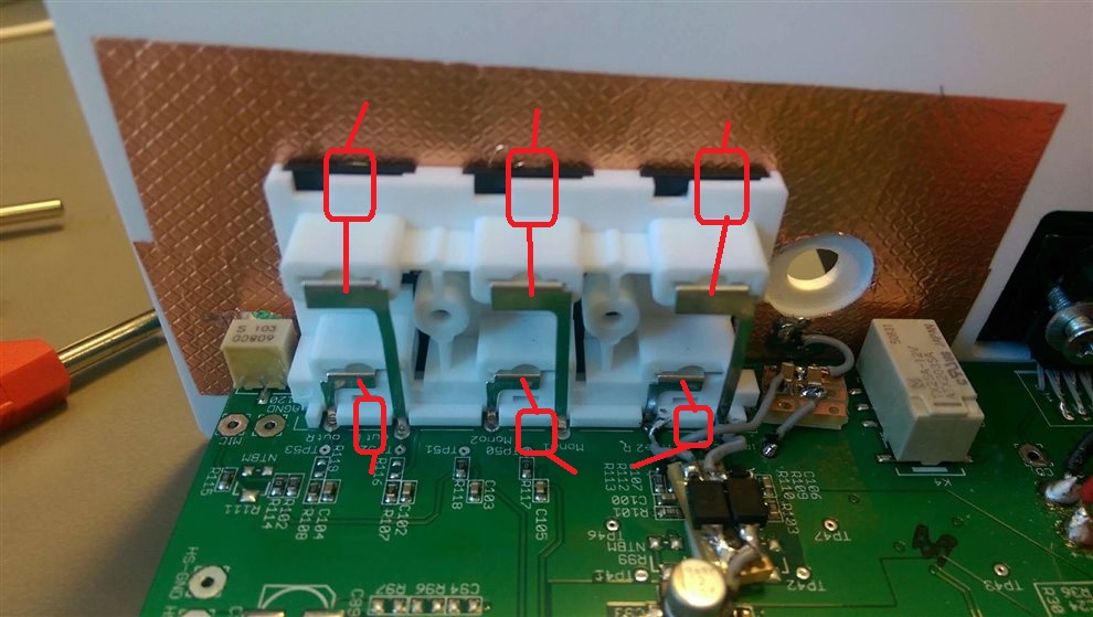
There are 2 diodes for transient suppression on Vin- but this is not enouf for making is pass ESD.

Looking for any solution that helps me pass ESD... replacements of opAmp(military version of TLC2274?), suppression diodes or schematic mods.


  • Hi Jon,

    the problems arise from your circuit, not from the chip. ESD currents must never flow through the circuit but must be shunted arround the circuit. This is especially true if you don't have a solid ground plane on your PCB. Take a low leakage TVS and connect it directly between the pins of input connector, from the input to signal ground. Connect signal ground to the metal case via a 10nF cap. Mount this cap also directly at the connector. Take care, keep the wiring as short as possible. Avoid pig-tailing. Each millimeter counts!!

    How does this scheme work?
    If ESD hits the cable screen, then ESD flows directly through the 10nF cap to the metal case. If ESD hits the input pin, then ESD flows through the TVS and then through the 10nF cap to the metal case. If you do the wiring properly only a very small portion of ESD is still flowing through the rest of your circuit.

    You should also improve the ESD protection scheme of your circuit: Move D13 and D14 to R112/R113 and R109/R110. Keep the distance between the ground pins of BAV99 and the 10nF cap at the input connector as short as possible. Connect a 100n cap from each +13V pin of BAV99 to signal ground. Keep also the distance between the ground pin of 100nF cap and the 10nF cap at the input connector as short as possible. It's best to have a solid ground plane for all these connections and the ground routing of the rest circuitry. You should also limit the voltage at these 100nF caps by the help of a TVS or other protection measures, so that the maximum supply voltage of TLC2274 of 16V is never exceeded.

    By using this hybrid grouding method with the 10nF caps most of the ESD is shunted arround the circuit. That's the way how ESD has always to be treated. Only by this ESD can be hindered from entering the circuit. This methode will work even better, if you can directly connect signal ground to the metal case at the input connector.

    Kai

  • Thank you very much! :)

    Unfortunately I do not have a chassis ground. It is a floating system with a virtual ground. I'm afraid it will be a bit more challenging.
    I will try with a fast TVS diode on the input and do the changes on the protection input diodes.

    The schematic shows only the part that fails. There are more TLC2274 op amps on the board, EQ section, splitters etc.
    There are in total 28 opAmps of 2274 but this input section is the only place that fails.

    I'm hoping a TVS on Line input will do the job but I'm not convinced.
  • Hi Jon,

    if you don't have a metal case, then take a piece of metal and form sort of a RF plane (radio frequency plane) for only the ESD currents. Or by other words, all the 10nF caps used for the hybrid grounding should be connected to this RF plane.

    But under no circumstances the ESD currents must be allowed to flow through the circuit! Using a solid ground plane might help then a bit. But it's much better to shunt the ESD currents all arround the circuit and away from the PCB.

    Keep in mind, how ESD is flowing when it enters your system. It wants allways to flow back to ground, which is protection earth or soil meant here. Mainly this is done by hopping from one cable to another. So, all the cables with their connectors should have this hybrid grounding to a suited RF plane.

    Kai
  • Adding to Kai comments - TLC2274 does have internal ESD protection or it would not be rated for 2000V HBM model and 1000V CDM - see below.

    What kind of supply voltage do you use?  If you use LDO or similar type (which cannot sink current), you MUST add the bi-directional TVS's to the inputs, which Kai alluded to, and/or place a zener diode (TVS) between the supply pin and ground with a breadown voltage of 16V or less so the supply voltage will be clamped below TLC2274 absolute maximum rated supply voltage.  Otherwise, any large ESD pulse at the input will result in the spike on the supply pin damaging the part.  The series input resistors alone shown on the schematic do NOT provide any protection because once the input voltage is above 13V, there is no path from supply pin to ground for the current to flow.  Even though bi-directional TVS's on the inputs may be sufficient to protect the part against ESD event on the input, they will not prevent damage due to over-voltage on either input or supply (most power supply overshoot during power-up) - see attached.

    7875.ESD_EOS.pptx

  • Thanks!

    Im using standard linear regulators. 78L05 x 2 and a LM317. These are fed by external smps power. There is a clamping diode between pluss and minus power.

    Very informative powerpoint. 

  • Thnx Kai

    Interesting consept that a RF plane... not sure I really got it.
    Lets say I make a metal sheet and make this as hybrid grounding. On the backside of a panel would be a suitable place to attach it.

    Step 1: TVS diode between the Line signal and metal sheet(RF plane)
    Step 2: 10n cap between shielded connector and metal sheet.
    Step 3: Metal sheet connects to my negative power with shortest possible way

    In this way ESD current will only pass thru my virtual ground?
    Could you draw a simple graphic drawing maybe?
  • Is there any special 10n cap that I should choose ?
  • Hi Jon,

    The signal grounds of input and output connectors are directly connected to the solid ground plane. For the 1M resistor a VR25 can be used. The caps are 10nF ceramics which should be rated at 1kV.

    Kai

  • Thnx!

    Been working on it today.:)

    I'm using a copper tape as an rf-plane. 50x90mm. And since I do not use an LDO I haven't added the resistor/cap to rf-plane. Hoping that's fine.

    Bidirectional TVS diodes are all there.


  • Hi Jon,

    looks interesting. :-)

    These are RCA sockets, female jacks, right? You could connect the ring of metal (signal ground) directly to the copper foil, right at the jack. Then you would not need these 10n caps. (The 10n caps would only be needed, if the RF plane was connected to protection earth, like in a safety class I product, for instance.) Solder the TVS directly from the center pins to the copper foil, then. If you connect the copper foil at the edge of PCB to the solid ground plane, you can connect the lower TVS also to the ground plane, like shown here:

    Kai

  • Thx

    Yes it's female RCA sockets. Made another board without those 10n caps. 

    Moment of truth will be tomorrow. 


  • Good luck!!!!!  :-)

    Kai

  • Hi

    Unfortunately the product still fails ESD. 

    At first we tought everything was fine... we did a brutal testing with series of pulses at 4kV, then 5kV. Equipment did fine on every touchable metal parts.

    We then adjusted the gun to deliver a negative pulse at 4kV... the eguipment did not like that! The first opAmp was fried

    I do not have a capacitor close to power pins at the opAmp. I believe it might help to absorb some energy. 

    Make a larger rf-plane maybe... Not sure where to go next. 

  • Well done, Jon! That the circuit now withstands so many pulses more than before is a huge progress!! :-)

    If you hit your circuit with an ESD pulse and the ESD protection scheme isn't perfect, as it isn't in the very most applications, the ESD current distributes among several paths. And it's important to strengthen each of these paths! And yes, it's extremely important to have the decoupling cap of OPAmp sitting as close as possible to the package!!! Every millimeter counts when it comes to ESD protection!!

    Kai

  • Hi

    I finally got the EUT to pass ESD... actually i didn't need any RF-plane this time. I tried out another opAmp with a higher ESD value. TLV4172.

    My problem was with negative 4kV. Was really struggling and making the RF-plane to be working but also production "friendly". Not easy at all!

    A colleague of mine found TLV4172. Same pins outs, package and power. Certainly better internal protection on this one!

    Anyway thanx a lot for helping me out. Learned a lot.

    I really appreciate all the comments !:)

    Jon Fredrik Våle

  • Congrats!

    Kai