A related question is a question created from another question. When the related question is created, it will be automatically linked to the original question.
If you have a related question, please click the "Ask a related question" button in the top right corner. The newly created question will be automatically linked to this question.
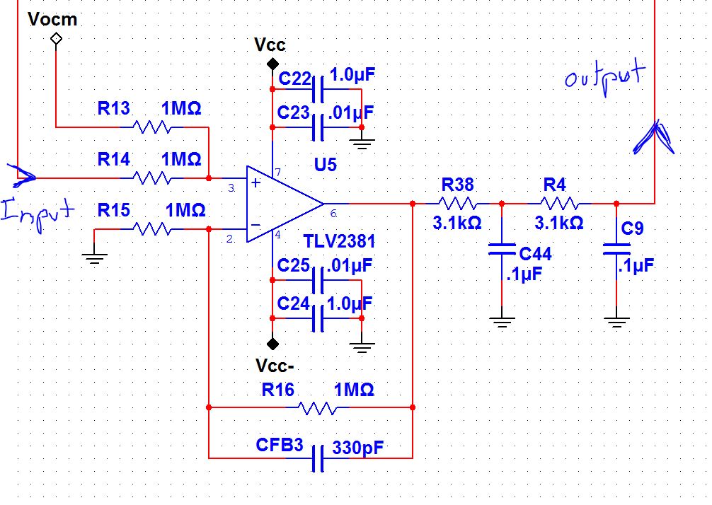
Can someone at least give me the output impedance of the TLV2381 so that i can find a similar model in SPICE to use since the TLV2381 doesnt have a model in Multisim or TI-TINA
The output impedance of this circuit, or the impedance looking back into the output node of the filter, will change with frequency. The impedance back through the filter and the TLV2381 complex output impedance must be considered. The feedback path impedance is very high and can likely be ignored. However, because the specific output impedance vs. frequency characteristics of the TLV2381 are not published, we could only guess how it's open-loop output impedance (Zol) changes with frequency. The CMOS drain-drain output stage of the TLV2381 and similar amplifiers produces a complex open-loop output impedance that can look like a pure R, R + jXl, or R - jXc, depending on the operating frequency range. This open-loop complex impedance will be tempered to an extent when feedback is applied and the amplifier operates in a normal closed loop fashion.
About the best way to get close to the answer is to simulate the circuit using a PSpice simulator such as TI's TINA Spice simulator - available for free download through the TI website. The TLV2381 does not have a simulation model, but you could model its Zcl as a low value resistor. However, the response would be that of driving a resistor and not that of a drain-drain output stage and the results may be off more than you would like. A good alternate would be to use similar amplifier, but one having a modern simulation model such as the OPA333. Its simulation model is very detailed and includes the complex open-loop output impedance (Zol) behavior across frequency. The filter and amplifier output can be back driven with a current source across frequency. A voltmeter placed across the current source can be used to collect the voltage level as the frequency is sweep. Although the TLV2381 and OPA333 are different amplifiers by design but there is enough similarity that the results should be more representative than would be obtained using a fixed resistor.
Unfortunately I can not find a model for this device or a specification for the open-loop output impedance (Zo) value. However, in a CMOS amplifier the open-loop output impedance can be roughly estimated using the following relationship: Zo ~ 1/(2*SQRT(k*Id)) Where "Id" is the class AB bias current that flows through the output transistors. In a CMOS amplifier this current can be estimated to be approximately Iq/2 because around half of the quiescent current of a device flows through the output biasing circuitry. Therefore as you can see devices with smaller quiescent currents typically have higher output impedances. This is not always the case but using when there is no alternative this provides a decent estimate.
The TLV2381 has an extremelly low quiescent current value of 10uA MAX. Therefore I would estimate that this device has an Open-Loop Output impedance in the range of 1k to 10kOhms at high frequency and is likely a 3-stage output impedance type device so the DC impedance will be greater.
That said, the output impedance of your circuit will be primarily dominated by the output resistors that are part of your ouput filter: 3.3k + 3.3k = 6.6kOhms of output impedance. This is because when a control loop is placed around an amplifier, the closed-loop output impedance must be used, not the open loop output impedance. The closed-loop output impedance (Zcl) is equal to the open loop output impedance divided by the loop gain of the circuit (AOL*B): Zcl = Zol / (1+ AOL*B).
Since your circuit is in a noise-gain of 2V/V (6dB), the AOL*B term will be very large at DC because there is plenty of loop gain left in your circuit. This part has a DC AOL of around 110dB so the AOL*B term will be (110 - 6dB = 104dB). So the Zol value of up to 10k will still be divided down by 104dB which is over 100,000X! So the contribution of even 10k of open-loop output impedance, Zol, at DC only contributes 10k/100k = 0.1Ohms in your circuit because this is the closed-loop Zcl value.
As the frequency increases the output impedance will increase of the amplifier because the AOL value decreases over frequency. However, at the same time the capacitors that are part of your output filter will begin to look like shorts to GND so the impedance of the circuit will remain low.
In summary at DC the output impedance will be dominated by your 6.6k of output resistance that is part of your output filter. As the frequency increases the capacitors that are part of your output filter will begin to dominate.
Regards, Collin Wells Precision Linear Applications.
I did a SPICE AC analysis of the circuit using another low power TI op amp and came up with ~12k to GND with the two stage filter. With only one stage it was about 6.2k. My question now is, the circuit above is only half of the output. It is the inverted leg of a differential output stage. Would the differential impedance be twice the single ended?
Looking back into the differential output I would actually think that the impedance would be twice because the two legs appear in series.
Also since you're creating a differential output you may consider creating a differential filter instead of just a single-ended one. Below is a like to a nice app note from Thomas that shows examples of combining more complicated single-ended filters into differential filters. The same principles apply to your circuit.
I simulated the OPA333 + low-pass filter circuit. One millampere was forced through the application circuit output node and swept across frequency. The impedance is 6.2K at dc and low ac frequencies as expected. Then, the impedance changes as the frequency is increased because of the filter's complex impedance and the amplifier's output impedance changing with frequency. You can see the results in the attached file. I plotted both the voltage amplitudes and their phases at the driving current source (IG1) and at the output of the operational amplifier (Vopa). It is evident how the initially very low, closed-loop output impedance (Zcl) results in very little og the backdrive voltage being developed across the amplifer's output impedance. Then, the voltage increases with frequency as Zcl increases but again decreases with increased frequency further as the filter's capacative reactance becomes lower and lower.
One thing about the simulation that have haven't quite figured out is the VM2 voltage scale plot which indicates the 6.2k. That would appear to be 6.2kV, but when I check the backdrive RMS voltage levels at 10Hz as shown on the file schematic they correspond to the 1mA peak IG1 current that I used. I tried changing the current to 100uA and obtained the same 6.2k peak value. I need to think about this a bit more.
Yes, the differential input impedance is twice that of the single-ended input amplifier.


