This thread has been locked.

If you have a related question, please click the "Ask a related question" button in the top right corner. The newly created question will be automatically linked to this question.

TINA-TI TLC2272A Model Question

Other Parts Discussed in Thread: TLC2272, INA128, UA741, TLC2272A, LM741, OPA171, OPA141, OPA140, OPA170

*EDIT* Sadly I just realized that the TLC2272 (while listed on TI's cross reference sheet as the replacement for AD822) is not a replacement in all aopplications. It's max supply voltage is only half of the AD822. Probably why the model simulation is failing.

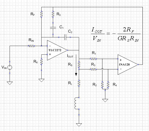
Hi, I have a conceptual Voltage to Current amplifier shown below. The generalized DC transfer function is also shown. It does not account for the current loss in the divide down resistors of the INA128 inputs. The resistors are used to keep the common mode input low for higher current drive. I have a few question, a couple are just to ensure I understand the operation of this circuit.

INA128 is set for a gain of 1. Both amps are driven by +/-15V supply (not depicted). Rin and Rs are 10k and 100 ohms respectively. R1-R4 are equal. Vin is set to 1V. The gain equation, again not accouting the loss in the R1-R4 network does work for positive input voltages with a feedback resistor upto about 5k. The equation implies that 6k feedback resistor would give about 12mA of output but I think the negative rail is limited at the higher current drive.

The real confusion stems from making the input voltage negative. The opamp doesn't seem to respond properly and I don't understand why. The output doesn't agree with the gain equation at all. Cadence Orcad gives the same results. However, if I replace the TLC2272A with the LM741 or uA741 it works just fine for any input voltage. Is there something I am missing with this model? Also is this op-amp not capable of driving a 1k load with 12mA? Am I hitting the maximum negative output voltage of the amp? If so is there a recommended replacement that gives a more dynamic output range but keeps the excellent offset and input bias specs this amp has? I am working in the -55 to 125 temp range as well.

Thanks for any help that can be provided


  • Hi Shawn,

    Likely, the TLC2272 output current will self limit well below 12 mA as indicated by Figures17 and 18, in the data sheet. That would prevent the circuit from producing the expected output as Vin is driven toward the output extremes.

    You mention that the TLC2272 maximum supply is half that of the AD822; yet, you mention that both amplifiers are being driven by +/-15 V supplies. You might be able to get away simulatingthe TLC2272  with +/-15 V supplies, but operating the actual product with these levels will destroy it. So I must assume that the actual supplies you are using with the TLC2272 do not exceed the +/-8 V (16 V between supply pins) maximum listed in the the Absolute Maximum Ratings table.

    The results you receive from Spice simulations are indicative of the simulation model accuracy. Simulation models have evolved radically over the years and the TLC2272 simulation model is an older generation Boyle model. That model type is much more simplistic than those developed for more modern operational amplifiers. The UA741/LM741 is a much older product than the TLC2272. Chances are its simulation model is older, simplier and its performance is less representative of the actual product's behaviors. The output voltage/current characteristics when simulated may be much different that what you would see with the actual device. The LM741 has short-circuit minimum current listed at 10 mA so it might not be able to supply 12 mA.

    Some modern TI operational amplifiers that are true +/-15 V supply devices, have low voltage offset and input bias current, and will sink/ source 12 mA are the OPA140, OPA141, OPA170 and OPA171. They are specified for the -40 to +125 C temperature range, but have operating range that extends down to -55 C.

    Regards, Thomas

    PA - Linear Applications Engineering