This thread has been locked.

If you have a related question, please click the "Ask a related question" button in the top right corner. The newly created question will be automatically linked to this question.

Issues with the OPA548 current limiting

Other Parts Discussed in Thread: OPA548

Hi,

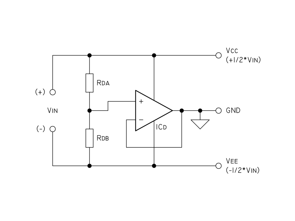
I'm doing a rail splitter, that follows the basic concept shown in the next schematic diagram:

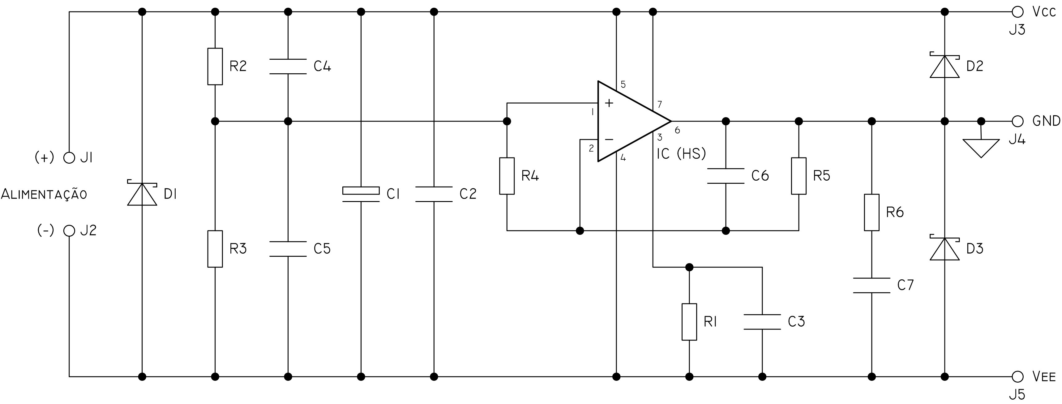
In order to eliminate noise, I've used a 100uF capacitor and a 100nF bypass capacitor across the supply and two 10nF capacitors in parallel with the resistors Rda and Rdb (those are 10K each), As for the current limiting, I've used a 22K resistor paralleled with a 10nF capacitor, from pin 3 (Ilim) to V-. I've tied pin 7 (E/S) to V+. I've used two free-wheeling diodes across the output and, of course, a zobel consisting of one 4,7R resistor and a 100nF capacitor.

The problem is that the OPA548 limits the current to around 700-800mA when sinking (output shorted to V+), and that current pretty much depends on the supply voltage. However, when sourcing (output shorted to V-), it behaves as expected, since the current is limited to 2A (Rlim = 22k). Why does the current limit doesn't work properly when sinking? Is it a defective design? A damaged chip? Or is it that the current limiting is only applied when the OPA548 is sourcing? I've tried everything! I've changed the resistor values, taken out the zobel and the diodes, untied the E/S pin from V+, and the behaviour is still the same! What is wrong?

  • Hi Samuel,

    My guess is that the OPA548 is oscillating. If you are just watching the ammeter on a power supply or DMM, you may not see the true peak current.

    Have you looked at the "GND" output with a scope to see if there is a high frequency (>100KHz) oscillation?This could be a small 100MHz squeak of a few hundred mV, or a several Vpp oscillation.

    Careful "grounding" your scope!!

    Note that "floating" your scope by breaking the ground pin is cheating. You are still adding extra capacitance to the "GND" point through the AC line and may actually "snub" the oscillation. Ideally the scope should be "grounded" to one of the rails and the GND node probed. Use a battery powered, truly "floating" scope if possible.

    You can also use a AC voltmeter between one of the rails and "Ground" to check for any AC voltages. Any AC voltage more than a few mV across the rails may mean an oscillation. Most hand-held DMM's can detect AC up to a few MHz.

    The most unstable op-amp configuration is the follower - which you are using.

    Do you have supply bypass capacitors on the load side (between "GND" and VCC or VEE)? This is a direct capacitive load on the output - which op-amps do NOT like. Even with a Zobel "snubber" - any bypass caps on the load side are "bypassing" the snubber....Low ESR ceramic caps directly on the output can really make an amp scream.

    One thing you can try is placing the OPA548 in an AC noise gain of 5-10. To do this; Set a non-inverting "AC gain" of, say 10. Add the feedback resistors R1 (1K) and R2 (9K) as shown in Figure 1, but tie R1 to the non-inverting input (Rd tap) through a 22uf cap. This will still give you a DC gain of one referred to the non-inverting input (though the output may be slightly noisier due to the AC gain).

    Are you sure the source supply is truly "floating"? Could there be a parallel "path" to ground through a test instrument or other circuit component? Is there more current being drawn while at mid-supply than you expect?

    Regards,

  • Whoops...Sorry...I'm used to these rail splitters oscillating when not shorted...

    You will need to look carefully at the opposite rail when shorting the output, or monitoring the current at the output or supply pins, to see if there is any trace of ripple, that would indicate an oscillation.  It is possible for the current limit to oscillate or "motorboat" if there is poor power supply bypassing or regulation.

    Regards,

  • Samuel,

    Paul's suggestions are good ones. Always check a circuit out with a scope for possible oscillations, even with a totally "DC" circuit.

    I'll suggest this possible change:

    This may help cure a number of possible ills. It raises the noise gain to avoid oscillations (including with capacitive load as we discussed in your previous thread). When you short to positive supply, it pulls the inverting input outside its common-mode range. This circuit should avoid that. I think the short condition may also turn on differential clamps on the input. This may help with that situation, too. I've had no time to check this out in detail and I travel tomorrow. Give this a try.

    Regards, Bruce.

  • Thanks Paul and Bruce,

    My power supply is linear regulated. I have no capacitive loads, and I even taken out the zobel. Indeed I saw a small ripple (273mVpp) when shorting directly the output to V+. That ripple would appear on the positive input as well, with a much smaller magnitude (5mVpp). Last night I've tested this with some resistive loads, and I could sink currents up to the limit of 2A without a problem. A direct short without using the ammeter would give a short circuit measuring 1.05A (read on the power supply display). This suggests that it is really an issue related with the common mode. But since I only need to guarantee 2A without shorting, that's OK for me.

    My conclusion is that direct shorts to V+ drive the inputs out of the common mode range. However, if the output limit is not triggered, or if it is triggered but not severely, it can sink 2A perfectly. Well, my objective is that the OPA548 can source or sink up to 2A under normal operation.

    Bruce, I've tested your circuit, but the noise increases considerably, and it offers poor regulation. I think those feedback resistors are too low and so it pulls on those 22K resistors on the voltage divider. Anyway, my circuit sources or sinks currents up to 2A if not shorted. I was making the wrong assumption when measuring those currents by shorting the output to V+. An op-amp is not a regulator. And maintaining that current constant under abusive load is not critical, not even a requirement.

  • Hi Bruce,

    I've decided to test your circuit again. I wrongly said that the regulation was poor. It seems that the breadboard had some problem, or it was the circuit at that time, I don't know. As you said, it is prone to noise. However, I've managed to mitigate it. as for R2 and R3 in the schematic (your R1 and R2), I've used 10K resistors. Across them, in parallel, two 10nF capacitors. I've used a third one across R5 (your R4). With the oscope, I've confirmed that the capacitor in parallel with R5 helped a lot. However, taking out the other two 10nF capacitors would result in a somewhat increased noise (a tiny oscilation). What do you think?

  • Samuel,

    Using your component number...  C1, C4, C5 are good and should not relate to oscillations in any way. C6 would appear to negate any improvement in stability that you might get from putting the amplifier in a gain condition. It would probably not affect any improvement in the current limit behavior.

    Did this circuit correct the current limit problem? Please provide all circuit values in any future posts.

    Regards, Bruce.