This thread has been locked.

If you have a related question, please click the "Ask a related question" button in the top right corner. The newly created question will be automatically linked to this question.

RRIO op-amp trouble

Other Parts Discussed in Thread: LM7705, OPA2188, LMV842, REF5010

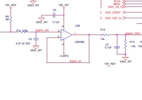
I have a circuit where I am using an op-amp in a gain of 1 buffer condition.  Rails are +12V and -0.237V (LM7705).  My input signal is a voltage divider and can range between 10V (open circuit) and 50mV.  Resistors change between the end of R9 (see below) and ground to give a variable voltage divider.  I feed the voltage through a low pass RC filter which consists of a 100K resistor and a 0.47uF cap to ground on the +IN terminal on the op-amp.

My current part selection is the OPA2188.  I would like to reduce the V+ rail to +10.4V.  However the OPA2188 is not a rail to rail input part.  I have been testing the LMV842, but I am getting errors as I approach 10V on the input (even with the original 12V V+ rail).  Is there some effect with the internal diodes I am violating?

  • Hi Charles,

    Can you further describe the "errors" you are seeing?

    It is normal to see a slight change in both amplitude and direction of the offset as you get near the positive supply, due to the transition of the input stages. This should only be a change of a few hundred microvolts or so...But the transition region should move with the power supply (usually about 0.8V  to 1.1V below V+). You can see these transition regions in the Vos vs. Vcm graphs on the LMV842 datasheet.

    ESD diodes should not be kicking in fully until you are past the rail - regardless of the supply voltage (10 or 12V). Is there *anyting* else on the input line that you are not showing? Someting that may break down?

    Hmmm...10V?....Ah!...Dumb question...What DMM are you using? Many bench DMM's switch between "Gigohm" input impedance and 10Mohm input impedance at 10V. Does your meter go "click" when you go over 10V? If you are seeing a sudden ~10% jump...then it may be because you now have a 10Meg to ground in parallel with the input. Many folks have been tripped-up by this "phenomenon" (because it is poorly documented in the DMM user manuals).

    Regards,

  • Paul,

    Not shown in the sketch, but the 10V is provided by an REF5010 part.  My error concern is with an open circuit for the resistor divider, 10V through the 1MEG, 100K and into the +IN pin I do not get 10V out of the LMV842.  I get about 8.9V.  As I add resistance to the voltage divider, the output is what I expect with the voltage follower.  For example, if I connect a 1MEG ohm resistor and divide the 10V in half, I get the expected 5V on the output pin.

    Works as expected with the OPA2188, but as I mentioned, I'd like to reduce the +V rail to 10.4V which then the OPA2188 would not work.  I see the issue with the LMV842 when +V is 12V or 10.4V which I do not expect.

    Charlie