This thread has been locked.

If you have a related question, please click the "Ask a related question" button in the top right corner. The newly created question will be automatically linked to this question.

OPA4188 SR Limit

Other Parts Discussed in Thread: OPA4188, OPA188, OPA2188, OPA4192, OPA4172, OPA4171

I'm wondering if someone can help me why our OPA4188 is showning SR limits of about 80KV/S (0.08V/uSec) instead of the specificaiton of 0.8V/uSec typ?

My circuit is a differential input gain of one using 100K ohm resistors.  Circuit is shown below.

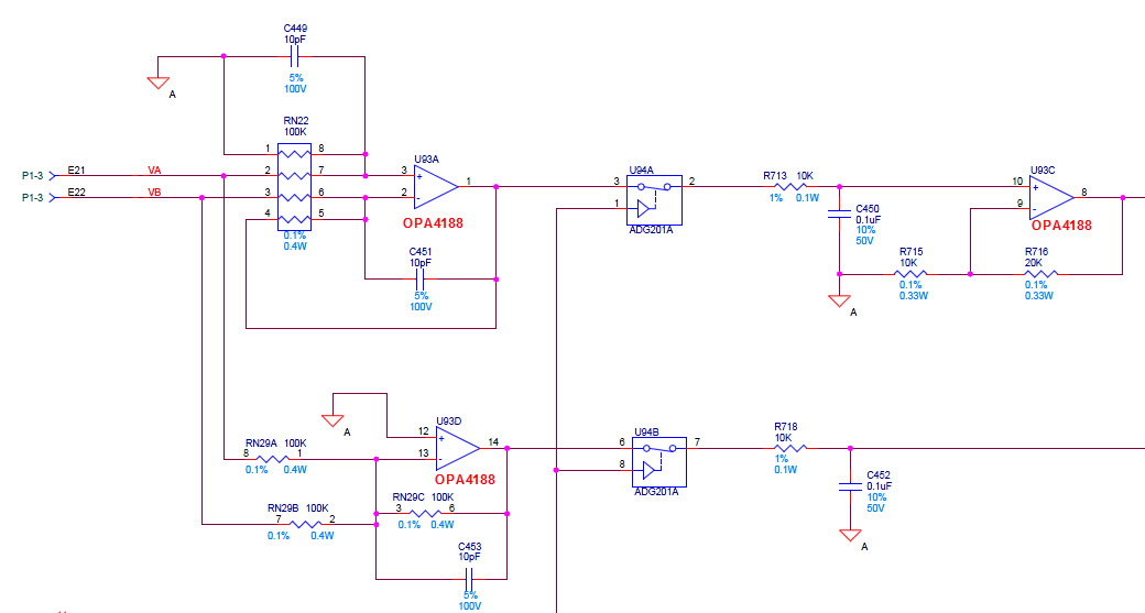
The inputs are sinewaves of about 9Vp and 4Vp for an output of about 5Vp.  I have captured the positive input and output in the waveforms below.

 1_16_2015.pdf

Does load have any effect on SR limit on this Op Amp?


Thanks,

John Gray

  • John,

    You have a low-pass filter in the feedback of the first op amp and in front of second OPA188 op amp with 1ms time constant (10k||0.1uF) which completely dominates the AC response by slowing it down.  This is not how slew rate should be measured -  remove the caps and see what happens.  Please see below OPA188 large signal response with no filtering.

  • Marek,
    Thank you for looking at this. The R and C's you are notiing are not in the feedback of the op amp. The waveforms you are looking at are on pin1 of the OPA4188 (the differental circuit). The only filtering I have is the 10pf across the 100K resistor (a 1uSec tal) which will not affect the slew rate. I agree I have a 1ms tal on the circuit in front of the second op amp, but that is not where i want the sinewave to come into. Pin 1 of U93A is where the output waveform is measured. The input waveform is on pin 2 of RN22. The circuit will make a differental input circuit with 100K's everywhere for a gain of 1 differentially from input to output (single ended). I should have 0.8V/uSec on the pin 1 fo the U93A, but I don't have 0.08V/uSec.
    -John Gray
  • John,

    The typical slew rate of 0.8V/us specified in the OPA2188 datasheet is a boosted rate and thus artificially increased by additional current being pumped into the input differential pair that only turns-on when an inverting input falls behind the non-inverting input by few hundred millivolts (the change in the voltage at the input is faster than the native slew of OPA2188.)  

    The native (unboosted) slew rate is a function of the steady-state current biasing the input transistors as well as the size of Miller compensation cap:  SR=gm/Cc; in case of OPA2188 the native slew rate is actually around 0.2V/us, thus closer to what you see in your application.  Therefore, the distortion to your sinusoidal waveform, especially on the negative slope, is most likely related to the native slew-rate induced distortion which limits the full-power bandwidth of OPA2188 below what is shown in the PDS graph - see below.

  • Marek,
    Thank you very much for answering this. I don't claim I know the miller or gm inside the IC, but I am wondering if reducing the resistor values to say 10K, would that increase the current into the input differential pair enough to increase the SR? I'm not sure I can do that in the real circuit. But that would help me understand the charater I do see.
    Thanks,-John Gray
  • John,

    The short answer to your question is no - you cannot change the inherent slew rate of the amplifier using external components; the current biasing the input differential pair is set inside IC.  Reducing the input resistor to 10k would only work if the input signal is slowed by low-pass filter, which according to your previous statements is not the case here.  

    If you absolutely need the precision of OPA4188 and higher slew rate, you could possibly create a circuit using OPA4188 inside the second (faster) amplifier's feedback loop that would do the trick but it would be more complex and costly solution.  Otherwise, you could try to use OPA4171, OPA4172, or even better soon to be introduced OPA4192.