This thread has been locked.

If you have a related question, please click the "Ask a related question" button in the top right corner. The newly created question will be automatically linked to this question.

LMV7235, LMV7239 - Input Common-Mode Voltage Range Violation

Other Parts Discussed in Thread: LMV7235, TLV3201

Hi,

I have a transimpedance amplifier (TIA) operating at ±5V supply rail whose output feeds into a LMV7235 comparator.  An issue arises when the output of the TIA undershoots momentarily to the negative rail which violates the input common mode voltage range of the LMV7235 comparator.  The comparator responds by pulling this node down to about -1V for 14ms.  I'm okay with this behavior since the TIA is only being used to modulate the comparator ON or OFF but the datasheet for this comparator states that this will result in an increase of input bias current. 

My question is how much will the input bias current increase by and if there are any reliability issues with operating the device in this manner?

Thanks, - James

  • Hello James,

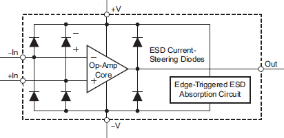
    The inputs have ESD protection diodes on the inputs to the supplies. Pulling the input below V- will cause the diode to clamp to V-. The clamp will start conducting about 500mV below V-.

    As long as you limit the current to below Abs Max (recommend < 1mA), there should not be a problem. Adding a series resistor will limit the current. So you want a minimum of 5V/1ma = 5k series resistor in line with the input.

    If this is expected to happen often, then an external Schottky clamping diode is recommended as the ESD diodes are not really designed for continuous use.

    Regards,

  • Thanks for succinct response, Paul!

    Just for clarification, the Abs Max quoted on the datasheet states ±10mA current at the input pins but you recommend derating that to less than 1mA, correct? I will most likely end up using a Schottky diode clamp as you suggested.
  • Hi James,

    Yes. The Abs Max is 10mA, but you really do not want to hit that limit. So I suggested <1mA to keep from pressing the limit. Less is better...

    Regards,
  • Hi Paul,

    I'm finding that I'm able to get these comparators to output an erroneous logic level due to ESD. It appears that an ESD event can inject transients on the inputs and supply rail causing it to violate the common-mode voltage range of the device which results in the output latching for tens of microseconds.

    I was able to replicate this behavior by simply applying a negative spike using a pulse generator on the inverting input while the non-inverting input was varied from 1V to 5V; the Vcc supply rail was fixed at 5V. At a reference voltage of about 2.6V or greater, a <1us -1V pulse causes the output to transition from high to low and latches for tens of microseconds. This response is identical to the response exhibited by the ESD event.

    My question is if you can elaborate on what the device is doing internally under these test conditions and, more importantly, if you have any suggestions to protect against this behavior.

    Thanks in advance,

    - James
  • Hi James,

    The official response is that you are operating the device outside the datasheet parameters, and operation is not guaranteed.

    Most likely what is happening is you are injecting currents into the substrate that charges up internal nodes (that are not designed to have charge) and it takes time for this charge to bleed off.

    At -1V, you are fully turning on the substrate diode (the bottom" of the die, along with the ESD diode). The low output impedance of the generator overwhelms the ESD diode - especially if you are cranking up the amplitude to get -1V.

    We are aware that negative spikes on the supply line before power-up will cause a start-up delay of about 1ms - but otherwise continues to operate normally afterward. You are probably seeing a similar effect.

    While the device is in the 'stunned" mode, random effects will occur since it is not properly biased internally. it would take me a few seconds to recover after being whacked in the face...which is essentially what you are doing to the comparator!

    You need to limit the current (current kills!). Series resistance in the input lines (resistor) can help limit the current - but the fast ESD pulse edge can shoot through the parallel resistor capacitance (~0.5pF) and whack the input.

    One solution for ESD is to place small (2pF) caps from the input line to ESD/Frame ground to shunt most of the pulse edge energy to ground. Also helps with EMI. The caps should be placed on the input side of the series resistor. It also helps to have some caps (or spark gaps) at the wire entry point of the board to dissipate as much energy as possible.

    Regards,
  • Hi Paul,

    Thanks for the insightful explanation.

    We are in fact seeing negative spikes on the supply line from the ESD event after power-up so that probably exacerbates the issue as you had alluded.

    Unfortunately placing shunt capacitors from the inverting/non-inverting inputs to frame ground in order to mitigate ESD susceptibility is not practical due to the application of this comparator circuit floating at several kilo-volts. What are your thoughts on placing the small caps between the input and the return node of the comparator?

    Any other suggestions you may have will be most welcomed. We're also opened to evaluating alternative devices that are more robust against this issue as well; candidates should ideally be form fit functional and have an open drain output stage.

    Thanks,

    - James
  • Hi James,

    Also be sure that the supply line is properly bypassed. The internal ESD diodes shunt the transients to the supplies (both V+ and V-). If the V+ line is "soft", the transient can be transferred to the supply line. Same with GND (V-). Put a small cap directly across the V+ and V- pins.

    Dealing with ESD is not easy. Remember that the goal is to shunt the high voltage around the circuit and back to ground. All the caps do is create an AC shunt. and move the path around.

    So placing the caps between the inputs would just shunt from one input to the other. The transient needs to get to ground.

    If there is high voltage, then external protection devices should be used. Do not rely on the internal ESD structures. They are really meant to protect the device during handling and minor EOS events.

    We also make ESD protection devices, as well as guys like Vishay, ON and ST.

    www.ti.com/.../esd-emi-protection-overview.page

    The closest drop-in replacement is the TLV3201 - you could try that one and see if it behaves better.

    Regards,