This thread has been locked.

If you have a related question, please click the "Ask a related question" button in the top right corner. The newly created question will be automatically linked to this question.

Rail to Rail Dc rectifier

Other Parts Discussed in Thread: LM6142

Hello All

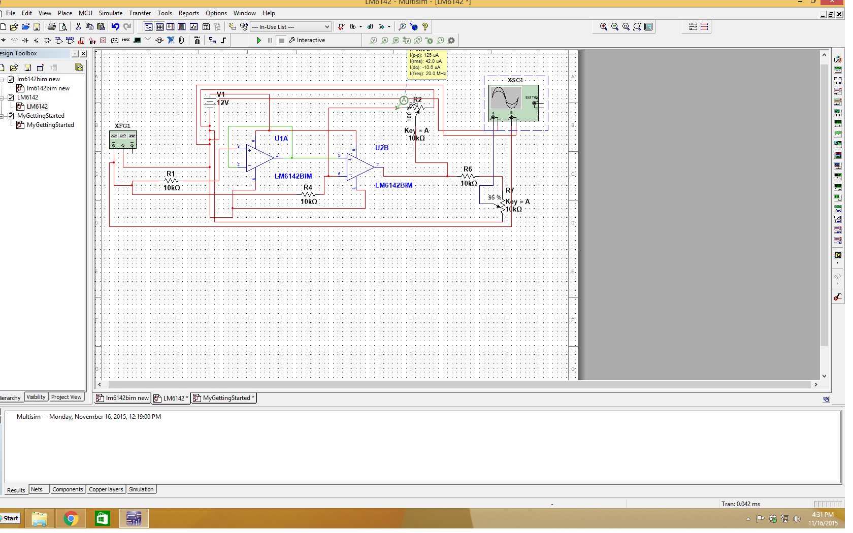
I am a undergrad student and I am trying to to make a full wave rectifier using rail to rail opamp. I want to supply  input sine wave with a frequency of 8 MHz. I am using LM6142BIM for rectification. However, when I increase frequency higher than 34 KHz the output is not whats desirable also there is a glitch in the output. Can anyone please look in this matter to help me out

Thank you  

  • Hello Akbar,

    Please provide a schematic of your circuit. There are several half-wave topologies. If you are doing what I think you are doing, you are close to destroying the amplifier.

    If the scope is showing what is at the device pins, then you are driving the input almost 10V below ground. This can be deadly to the op-amp. The abs max is -0.3V below V-, you are going -10V.

    The amplifier is taking time to recover after the input goes below ground. Notice it occurs at the zero cross on the positive going side. Most likely charge has been injected into some internal junctions and it is taking some time to dissipate. This is not the intended operation of the device!

    Also - the LM6142 may not be fast enough to give a clean output at 8MHz and 10Vpp. The Slew Rate formula shows a max frequency of 350KHz. You will need a op-amp with a slew rate of greater than 520V/us to get 10Vpp at 8MHz.

    Google "Active half wave rectifier", and you will see many different topologies.

    Regards,
  •  Thank you for the reply... i will attach the circuit diagram

  • Thanks for the reply here is the circuit Diagram i used