This thread has been locked.

If you have a related question, please click the "Ask a related question" button in the top right corner. The newly created question will be automatically linked to this question.

Behaviour of LMH6644 outside of input common mode range

Other Parts Discussed in Thread: LMH6644

I have a circuit using an LMH6644 as a 4-way unity buffer which is marginal in terms of input common mode range. The positive power supply to the LMH6644 has a minimum theoretical value of 3.26 V, and the input to the buffer has a maximum theoretical value of 2.35V. This violates the input common mode range of the LMH6644 - which could be as little as V+ - 1.4 at temperature extremes = 1.86V.

My question is - what is the expected behaviour of the LMH6644 under these conditions and in this circuit topology? I can accept truncated output voltage, but not other gross waveshape distortion, oscillation or phase inversion.

I realise that the best way to do this is using a higher input power supply rail, but I would obviously like to avoid this if possible.

  • Hello,

    I think your LMH6644 output will be "well behaved" (though non-linear) under the circumstances you have described where the input CM voltage range is exceeded.  there will be no output phase reversal or phase inversion as you've put it.

    There is a paragraph in the datasheet which I've quoted below:

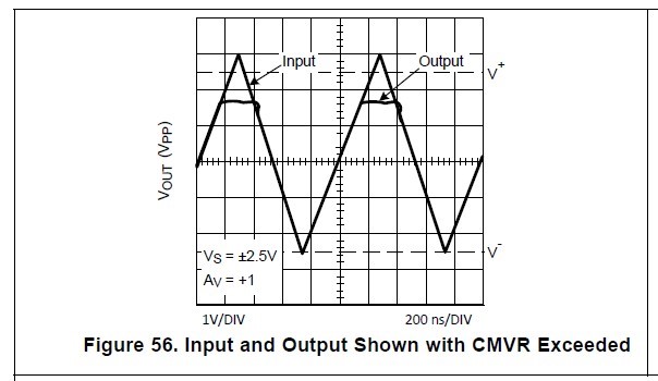
    "This device family was designed to avoid output phase reversal. With input overdrive, the output is kept near supply rail (or as closed to it as mandated by the closed loop gain setting and the input voltage). See Figure 56.

    However, if the input voltage range of −0.5 V to 1 V from V+ is exceeded by more than a diode drop, the internal ESD protection diodes will start to conduct. The current in the diodes should be kept at or below 10 mA.

    Output overdrive recovery time is less than 100 ns as can be seen in Figure 57."

    I think the Figure 56 waveform shows pretty much the conditions of your circuit and shows that output is flat near V+:

    Hopefully this answers your questions.

    Regards,

    Hooman

  • Thanks very much for this - I think I somehow skipped over this part of the datasheet (probably because I was searching for phase inversion, not phase reversal which as you point out is a much more correct phrase!).

    I can confirm that this is observable in the built circuit too - thanks for all your assistance.