This thread has been locked.

If you have a related question, please click the "Ask a related question" button in the top right corner. The newly created question will be automatically linked to this question.

OPA374 offset voltage

Other Parts Discussed in Thread: OPA374

hi!

I am using OPA374 in differential configuration to sense motor current.

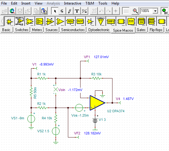
I have done DC simulation with same components i used in my circuit:

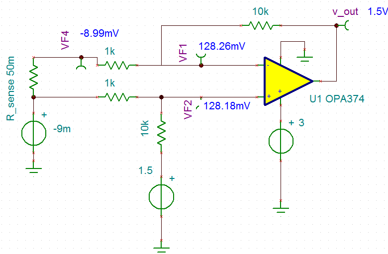
i added -9mv voltage source because the sense resistor is tied to digital ground and when i measured the voltages i had this potential difference between analog and digital grounds. during measurments no current is flowing trough r_sense .

my problem is that i get different result (as compared to the simulation ) my VF2 is close to 128mv but VF1 is 126.6mv and there for my output is not 1.5v and is about 1.487v.

i whould be very happy if some one can please explain why i am getting this voltage offset?

best regards

MARK

  • Hi Mark,

    The OPA374 simulation model has only 77.9 uV of voltage offset modeled. That is optimistic for a real device, but can happen because it is within the normal distribution.

    When I model your circuit in TINA, I find that it takes adding about -1.25 mV of voltage offset in series with the OPA374 non-inverting input for the output to be at 1.487 V. Internal voltage offset can be modeled as a voltage source in series with the non-inverting input. You can see this in the circuit below. 

    The OPA374 has a specified typical voltage offset of +/-1 mV, with a maximum of +/-5 mV. The device you have in your circuit is close to the typical. Voltage offset is a normal op amp electrical characteristic.

    I've attached my TINA circuit should you like to evaluate your circuit more.

    Regards, Thomas

    PA - Linear Applications Engineering

    OPA374_offset_01.TSC

  • hi Thomas

    thank you very much for your reply .
    i am using this circuit to drive 12 bit ADC , can i compensate this error in my code?
    as i understand the offset error reacts an the output with no regard to input so i am thinking to measure my output with 0 current in R_sense and the use the measured value in my code.
    am i right?

    best regards
    Mark
  • Hi Mark,

    The voltage offset and any gain error contributed by the op amp circuit and the ADC that follows can be compensated for in software. In fact, that is the way it is almost always accomplished.  

    I have attached a couple of PowerPoint slides that were developed by our Precision Amplifiers SAR Converters group. They describe and illustrate the gain and offset errors of a converter which could include those received at the converter input. It is the sum total of the errors that would be compensated for by the processor that follows the converter.

    Regards, Thomas

    PA - Linear Applications Engineering

    ADC_and calibration.pptx

  •  Thomas 

    thank you very much!

    Mark