This thread has been locked.

If you have a related question, please click the "Ask a related question" button in the top right corner. The newly created question will be automatically linked to this question.

TL082 Application

Other Parts Discussed in Thread: TINA-TI

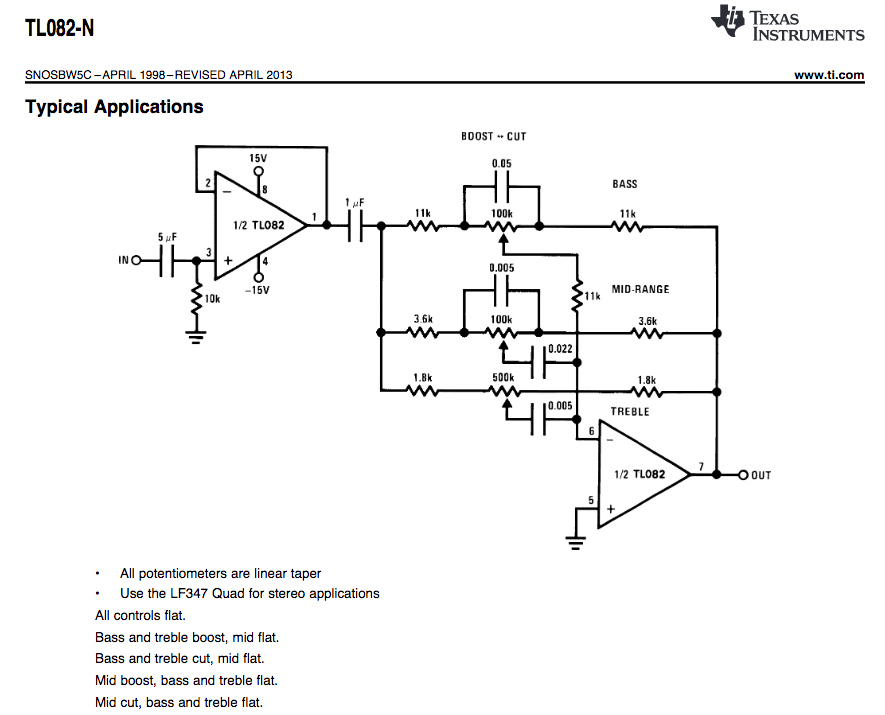
I am new to this field and I am trying to implement this 3 tone-control circuit. I have three questions:

Capacitance values are listed, should all capacitors in this circuit be aluminum capacitors?

For an additional volume control for full volume to no volume, I think I would need one more potentiometer, but what resistance value should it be and where would it go? I'm guessing it would go into the input or output of the first amplifier that I think is being used as a buffer?

For the other three potentiometers, it appears to me that the bass and mid-range ones have values of 100k and the treble one has a value of 500k, but I cannot find a digipot that has a resistance value as high as 500k?

  • Hello John,

    Sorry for the delay in a response.

    For a high performance low distortion design, I recommend using C0G/NP0 type capacitor. This article describes the performance difference between C0G/NP0 and X7R type capacitors.

    The resistance value for the volume control potentiometer can really be anything you want. Keep in mind that the higher the resistance value the higher the noise, but the lower the resistance value the more power the circuit will consume. A 10k or 100k ohm potentiometer should work.

    Using a 100k ohm pot for the treble portion of the circuit should be ok. Using a 100k ohm potentiometer will slightly change the frequency response of the treble circuit. You might want to increase the AC coupling cap on the output of the first amplifier to give you the same frequency response as if you were to use a 250k ohm potentiometer. I recommend simulating the circuit to see if it will give you the frequency response you are looking for. I have attached a TINA-TI simulation circuit for you to play around with. I have used all ideal op amps in the circuit to simplify the design so you can see how changing the potentiometer values effects the circuit response.

    This simulation circuit will also help you in how you want to implement a volume control circuit.

    You can download the free TINA-TI software here.

    -Tim Claycomb

    3 tone control circuit.TSC

  • Tim, thank you very much for the thorough response. I have been trying a lot of difference analysis modes with TINA, but I can't seem to reproduce anything like the frequency sweep graph shown in the datasheet. Which tool (AC analysis, signal analyzer, etc.) should I use to get the frequency vs gain graph, like the one shown below, and the voltage pins should be following the potentiometers, right? The bottom screenshot is the result that I am getting...

  • Hi John,

    The frequency sweep graph you show has five different test cases on it, all measured at the output of the second amplifier (VF1 in the TINA-TI schematic). Each test case has a different setting for each potentiometer to give a different frequency response. The test cases are listed below along with the potentiometer settings.

    Note 1: All Controls Flat (Meaning the potentiometers are all set to 50%)

    Note 2: Bass and treble boost, mid flat. This means that the bass and treble (low and high frequencies) will be increased while the mid frequency range will remain flat. (Bass potentiometer setting = 0%, treble potentiometer setting = 0%, Mid-Range potentiometer setting = 50%)

    Note 3: Bass and treble cut, mid flat. This means that the bass and treble frequencies will be attenuated and the mid range frequencies will remain flat. (Bass potentiometer setting = 100%, treble potentiometer setting = 100%, Mid-Range potentiometer setting = 50%)

    Note 4: Mid boost, bass and treble flat. (Bass potentiometer setting = 50%, treble potentiometer setting = 50%, Mid-Range potentiometer setting = 0%)

    Note 5: Mid cut, bass and treble flat. (Bass potentiometer setting = 50%, treble potentiometer setting = 50%, Mid-Range potentiometer setting = 100%

    I have attached another TINA-TI file with the bass, mid-range, and treble portions of the circuit labeled. You can test each one of the test cases above by adjusting each potentiometer to the correct setting (%) and running an AC analysis. To run an AC analysis go to Analysis (top of the screen) => AC Analysis => AC Transfer Characteristic and input the frequency range you would like to sweep. To change the potentiometer settings, double click on the potentiometer => adjust the category Setting [%]. The TINA-TI file I attached is set up to run test case 5.

    I hope this helps! Please let me know if you have any other questions.

    -Tim Claycomb

    3 tone control circuit rev2.TSC