Hi,
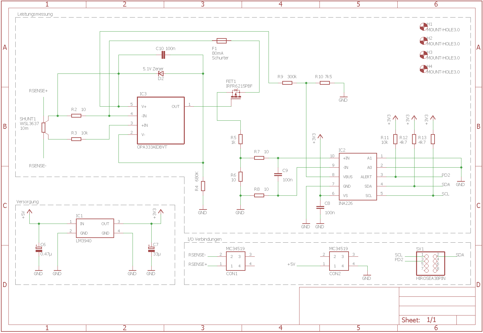
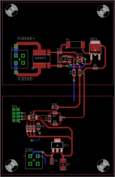
I currently try to build my own power measurement with the help of the application note TIDA-00528 (40 V to 400 V Uni-directional Current/Voltage/Power Monitoring Reference Design). I changed some parts from the schematic because I only need to measure 100V and 5A at maximum. The schematic and the layout is attached. I use the INA226 and the OPA333. The Shunt Resistor is a WSL3637 from Vishay.
The main problem that I’m facing is that I can measure a voltage drop across the Shunt Resistor (10mOhm, 1,5A) of 15mV but I can’t measure this voltage drop across the other 10Ohm Resistors (R2, R6). I can’t see any mistake if I compare my layout to the one from the Reference design.
My load is currently a heating cartridge and I use the Statron 3221 as a power supply. The INA is powered by an Arduino UNO R3 or rather the LM3940. I also tried to read data from the INA and that seems to be fine, however the readings are all zero because there is no voltage drop developed across the resistors.
Did I connect the VBUS Pin in the right way for a High Side measurement?
Is the IRFR6215PBF a suitable substitution for the IXTT16P60P that was used in the application note?
I have a voltage divider at the VBUS Pin with a ratio of 40 (300kOhm / 7,5kOhm). Is there a problem with the ratio because in the application note there was binary ratio of 64 in use?
Thank you in advance.


