This thread has been locked.

If you have a related question, please click the "Ask a related question" button in the top right corner. The newly created question will be automatically linked to this question.

OPA835 as a Laser Diode Driver - Stability

Other Parts Discussed in Thread: OPA835, OPA836

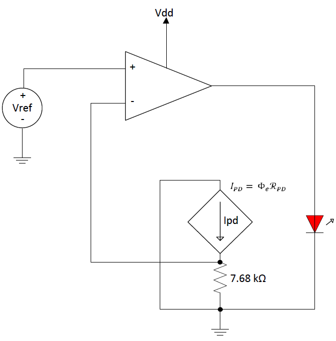
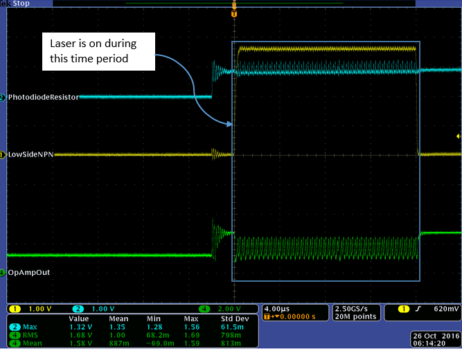
I am working on a design that incorporates an OPA835 to control the current pumped into a semiconductor laser diode. The feedback of the control loop utilizes a Si photodiode that is part of the laser diode packaging (schematic below). When I breadboard this circuit and use a DC reference of 800 mV, the op amp output is oscillating (the oscillation is approximately 1 Vp-p at 6 MHz) when the laser is turned on (the laser appears to be operating correctly). Based on the open loop phase characteristics of this op amp I am wondering how this is happening and what may be done to reduce the instability. When I remove the photodiode from the circuit and replace it with a voltage equal to Vref, the control loop is very stable.


Parameters:

Vdd = 3.6 V

Vref = 800 mV

Laser Diode Forward Voltage Drop = 2.2 V

Laser Diode Current = 12 mA

Photodiode Capacitance = 10-20 pF

Closed Loop Gain = 2.75 (Vref = 0.8 V, Vout = 2.2 V)

-Andrew


  • Hello Andrew,
    That is certainly an interesting circuit. The feedback is optical rather than electrical. So the way the circuit works is that the loop is going to try and force It 0.8V/7.68kohm = 0.1mA (approx.) of current flowing through the photodiode. Depending on the sensitivity of the photodiode the appropriate amount of current is then forced through the laser diode to keep the loop stable. Is that how you analyze this?

    Have you biased the photodiode (PD) circuit correctly? I don't think the photodiode circuit will work correctly the way you have connected it. If you have connected the PD circuit so that it is reverse biased then its cathode is connected to the inverting terminal and the anode is connected to GND: i.e the diode is sinking current to GND. If that is true then the other side of the 7.68kOhm resistor should be connected to Vdd rather than GND otherwise KCL is violated. Your thoughts?

    -Samir
  • Samir,

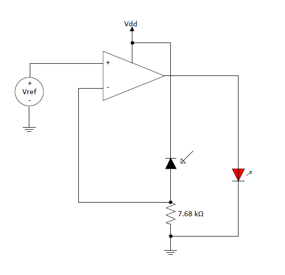
    You are correct in the first paragraph. As far as the connection of the photodiode, the cathode connects to Vdd and the anode connects to the 7.68k resistor, reverse biasing the photodiode. When the photodiode is illuminated by the laser, reverse current flows through the photodiode, dropping voltage across the 7.68k resistor. It is behaving as if the feedback loop has little to no phase margin.
  • Andrew,

    You said " the cathode connects to Vdd and the anode connects to the 7.68k resistor, reverse biasing the photodiode"...that is not what your circuit above shows. I do not see any connection to Vdd. Can you please draw out the corrected circuit or let me know if I missed anything.

    I cannot run a true loop gain analysis here like in traditional opamp circuit because the opamp is running open-loop electrically. The loop will be stabilized as long as the optical feedback system is much faster than the opamps bandwidth. Do you have some documentation for this particular control circuit. I would like to read some analysis on this circuit to ensure my understanding is correct.

    Samir
  • Samir,

    Below is the updated schematic. Unfortunately, the laser diode datasheet does not document transient characteristics. Based on similar laser diodes, however, I would estimate a 10-30 pF photodiode capacitance.

  • Andrew,

    Can you please add a 100 ohm resistor between the opamp output and the laser diode to isolate any capacitance from the diode. I am not sure if that will work but its worth a try.

    The next thing you can do is to add a large cap in parallel with the 7.68 kohm resistor to create a low impedance path on the PD side for fast transients.

    You could also try a faster opamp like the OPA836.

    What is the sensitivity of the photodiode? Lets assume the current required from the laser diode is 1mA (sensitivity = 0.1), then the opamp needs to slew at 1mA/10pF= 0.1e-9 = 100V/usec. The SR of the OPA835 is 160V/usec....its possible we don't have enough margin for error and a faster amplifier like the OPA836 will do the trick. Also, if you are bread boarding all this then there may be parasitic inductances that are slowing the control loop down.

    -Samir
  • Gentlemen,

    If I may suggest, the stability issue here is most likely simply due to the phase shift introduced by the feedback, in particular the 10-30 pF photodiode capacitance with 7.68 kOhm load resistor stands out. I don't think you would expect the OPA835 to be stable in a unity gain follower circuit with 7.68 kOhm feedback resistor and a 10-30 pF additional capacitance to ground at the inverting input.

    Probably it would be useful to measure the open-loop response from the laser diode drive voltage (with a resistor included in the circuit - this is important so that a reasonable large voltage swing on the opamp output like 1 V or so is used to cover the relevant range  of drive currents) through to the photodiode current, and measure the photodiode capacitance, and then create some SPICE model for the current response and see what it takes to stabilize the circuit.

    I would guess that a capacitor from the OPA835 output to inverting input, or perhaps an R+C in series with perhaps another smaller C in parallel, will stabilize such a circuit. Without such a direct feedback network though there is way too much gain for stability here.

    I hope this comment may help. I do apologize if I am saying anything wrong, I am speaking from experience with similar circuits but of course I haven't done any work on your particular case and much depends on the details of response of the laser diode and photodiode.

    If you make this work please post your final circuit as others (myself included) might want to make use of this someday, thanks!

  • Hi Gerard,

      If the loop was closed, then I agree....the loop gain analysis would show additional phase from the noise gain zero added by the 7.68k and 10pF cap. However in this case the amplifier is running open-loop. The only closed-loop system control is optical.

    Can you please draw out a TINA schematic on how you would do the loop-gain analysis for this particular setup. I tried but was unable to find a point to close the loop to get the "Beta" feedback factor.

    -Samir

  • hi Samir,

    I'm afraid I myself don't have any specific information about the open-loop response of the laser diode and photodiode.

    But for the sake of argument assume that the laser diode response is infinitely fast, not true of course. And assume there is no time delay (electrical or optical) involved. And assume the photodiode response (photons -> current) is also infinitely fast (which is maybe a somewhat reasonable approximation).

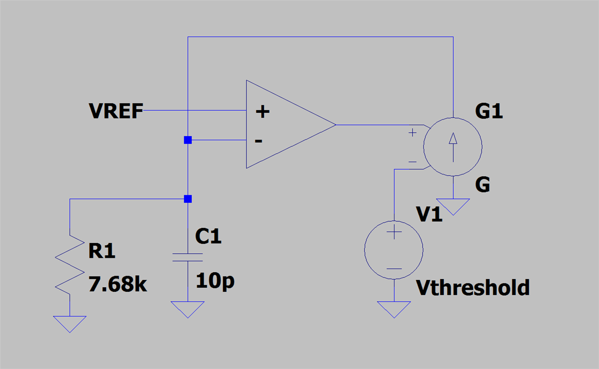
    Then equivalent circuit would look like this

    Where Vthreshold is the voltage (applied to the resistor+laser diode) that corresponds to the threshold of lasing, and G is the effective transconductance from laser + resistor driving voltage to photodiode current. I think Andrew can give these things from the datasheets, once the series resistor of the laser diode is picked.

    Clearly, this circuit is not going to be stable as such, at least not unless G is very small. It's really no different than having a 7.68k feedback resistor and a 10pF extra capacitance on the inverting input in a unity gain amplifier.

    In reality, the laser diode must have some time response that needs consideration too. I think what's needed is to measure the open loop response and then model it (inserting some poles and maybe even time delay between the opamp output and the G device in my circuit above).

    My apologies for drawing in LTSpice rather than TINA but it is what I work with here...

  • ** Root cause identified **
    None of the stability recommendations produced any noticeable improvement.

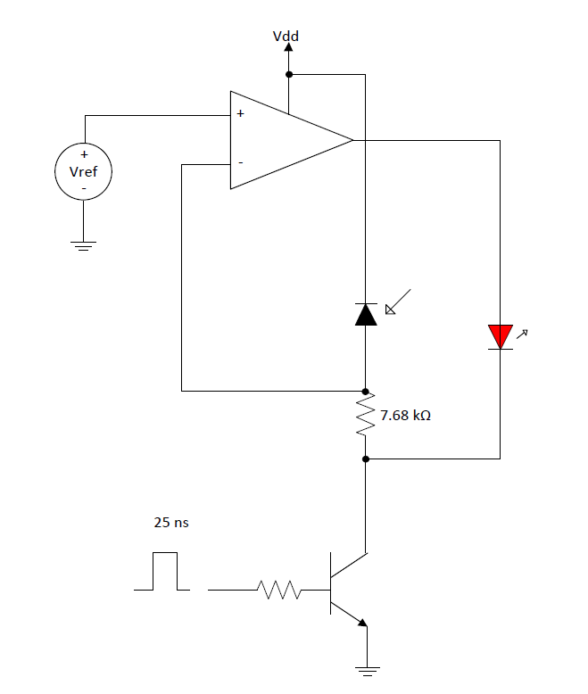
    An interesting observation with the above circuit is that is will respond to a 25 ns pulse when the laser diode ground is replaced by a low side high speed transistor. I measured a 10 ns delay between the low side switch activity and the optical output pulse from the laser (measured with an external high speed photodiode). It is when the drive pulse widens to 1 us or greater that I observe the periodic oscillations.

    What seems to be happening is the op amp is being overdriven when driving the laser diode, in turn going in and out of shutdown (or possibly the phase margin lessens at heavier loads). If I place an intermediate transistor drive stage (PMOS) and swap the inverting and non-inverting inputs, the circuit operates as expected - no instability/oscillations.

    Any ideas as to why the 12 mA load (laser diode) on the op amp would cause this problem?
  • Andrew, can you please draw out a rough schematic of the modified circuit with the high-speed transistor.
  • Andrew,

     In this case the loop is closed around the amplifier. This could be analyzed in 2 scenarios:

    1. Transistor OFF - In this case an impedance model of the laser diode will be needed to do the loop gain analysis. We already know the photodiode capacitance. Once these elements are added a loop gain simulation can be done to check stability and phase margin.

    2. Transistor ON - The model of the transistor can be included in the loop gain analysis to recheck stability.

    -Samir