This thread has been locked.

If you have a related question, please click the "Ask a related question" button in the top right corner. The newly created question will be automatically linked to this question.

INA333: Input bias current with AMC1200 output at input

Part Number: INA333
Other Parts Discussed in Thread: TIDA-00440, AMC1200,

I am designing a circuit similar to reference design TIDA-00440 - Leakage Current Measurement for Determining Insulation Resistance. I am using the combination of the INA333 and AMC1200 to detect the insulation resistance and obtain a 250mVpp differential signal with a output CM voltage of ~2.55V (VDD2 @ 5V). I need to translate the differential signal into single ended and feed it through a single ended ADC with FS 2.048V.

I was looking at using the INA333 to do the job. The manual mentions to have some kind of return path for the input bias current so the CM voltage does not float and change over time. Based on my simulations in TINA SPICE, the voltages looks good, but when I add any resistors to GND at the input of the INA333, it takes a very very long to complete and I do not think that it converges.

Any suggestions for what should be done with this type of setup for the input bias current or is there a better way to implement the DIFF to SINGLE stage?

  • any suggestions please?
  • Hi David,

    Sorry for the delay here, can you share your TINA schematic? The AMC1200 has a fixed gain of 8, so the +/-250mV input would be coming out at +/-2V. If you need to send that into a 0-2.048V single ended ADC, you would need to attenuate the signal by ~50%.
  • GFM.TSC

    Attached is the spice circuit. The output of the INA333 is a 0-2V since the input is 250mVpp. The VINN is basically static with a DC offset, while the VINP is swinging from 0-250mV.

    Thanks

    -David

  • Hi David,

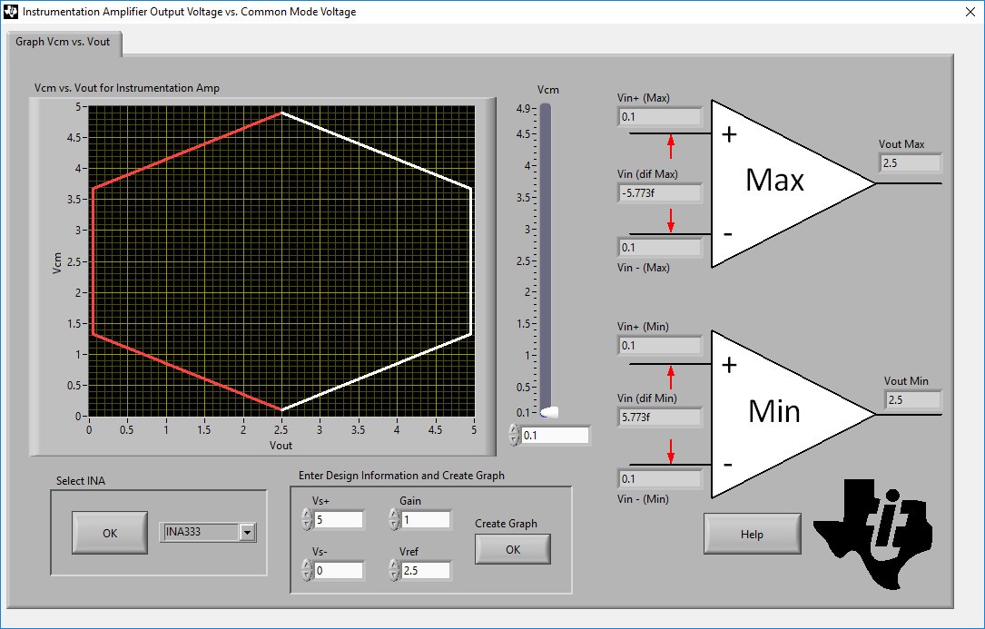
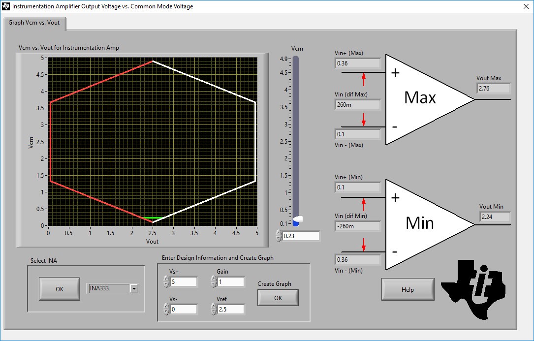
    It looks like you might be running into common mode issues on the INA333.  There is a handy calculator tool located here that you might find useful:

    With Vcm of ~100mV, the output of the INA is stuck at 2.5V:

    If the Vcm is boosted to ~230mV, you can get the output to swing around 2.5V to the input to VINP of the AMC1200:

  • I want the output of the INA333 to swing from 0-2V, NOT around 2.5V. Based on the SPICE, it does not show any saturation due to common mode. The input common mode at the output of the AMC1200 into the INA333 is 2.55V with 250mVpp swing. Based on the datasheet for V+ = 5V and Vref = 0V (Figure 21), the output should be able to swing 0-2V with no issues.

    Back to my original question, what should the return path be for the input bias current for a setup with the AMC1200 and the INA333. When I try to put high impedance balanced resistors to GND in the model at the input of the INA333, the simulation takes a long time and does not even complete. I do not want the balanced resistors to affect the voltage swing between the AMC1200 outputs, as I want to maximize the usable range.