Other Parts Discussed in Thread: OPA604, OPA140
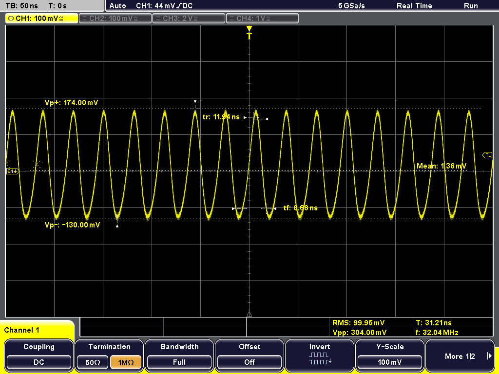
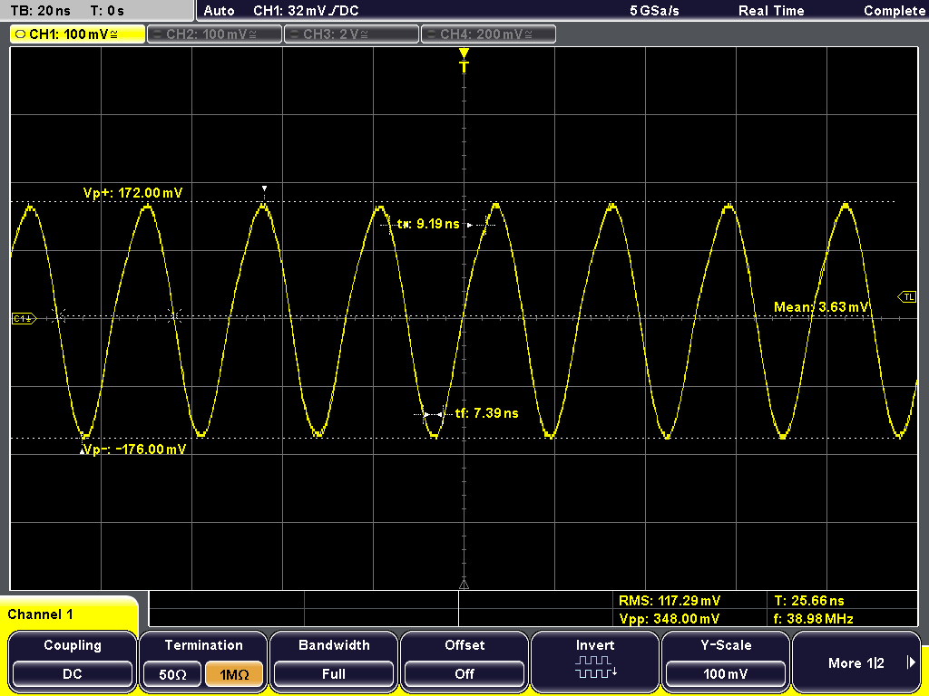
In a recent design update, we replaced an OPA604 with an OPA827 in a position as a voltage follower (buffer) at the input of an instrument. The input arrives on a BNC connector and feeds the amplifier's non-inverting input through a CM ferrite with a 1MOhm resistor to ground. All works well except when the input has an unsourced BNC cable attached (approx 300pF), when the OPA827 oscillates at about 400mV pk-pk with a surprisingly pure and stable frequency in the range 28 - 40 MHz depending on the length of attached cable. The oscillation appears on the non-inverting input as well as the output, so if you connect the open end of the BNC cable to an oscilloscope, you can observe the sinewave. Replacing the CM ferrite with shorting links makes no difference.
The OPA827 we use is the OPA827AIDGKT part (VSSOP package), fed from +/-15V rails and laid out on the CS of a 10-layer PCB with an analogue ground plane as the next layer 100um below the CS. The OPA604 did not behave in this way in an otherwise identical circuit.
The oscillation can be tamed by placing a low value resistor (220R) in the track from the amplifier output to its inverting input, but it's not a solution that works over all types and lengths of cable. The oscillation is not seen when the BNC cable is sourced from a low or medium-impedance ouput, as it would be in normal operation.
I would like some understanding on how the OPA827 can behave in this way, as the oscillations seen are at frequencies where, according to the data sheet, the device has a loop gain of substantially less than unity. In addition, what mechanism inside the part drives an oscillation out of the non-inverting input? Finally, do you have any suggestions on how I prevent the oscillation occurring under all conditions of input capacitance?