This thread has been locked.

If you have a related question, please click the "Ask a related question" button in the top right corner. The newly created question will be automatically linked to this question.

OPA4188: Strange sine distortion

Part Number: OPA4188
Other Parts Discussed in Thread: TINA-TI, OPA188, OPA1654

Hi,

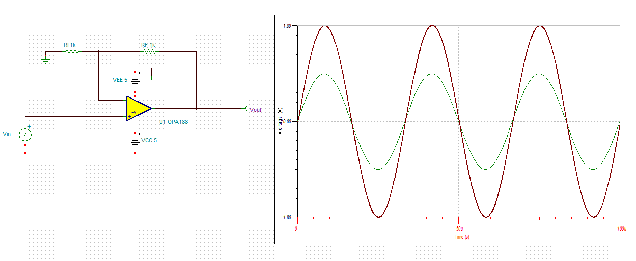
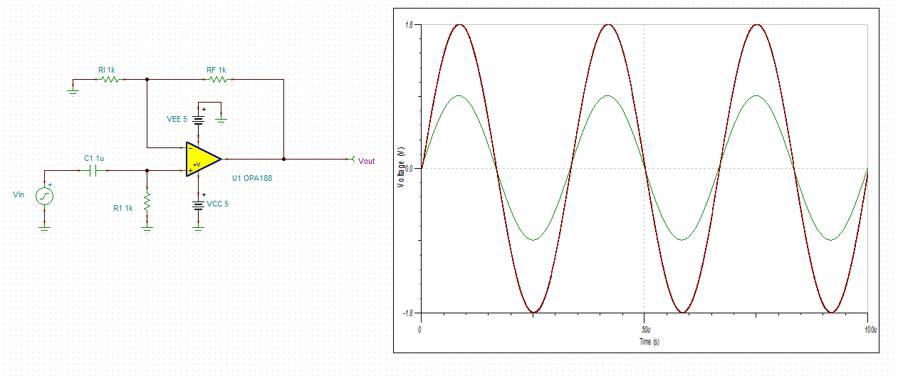
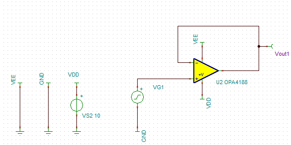
I am designing an amplifier with the OPA4188 and I have strange results. The circuit works a expected except a strange distortion. Here is the test circuit :

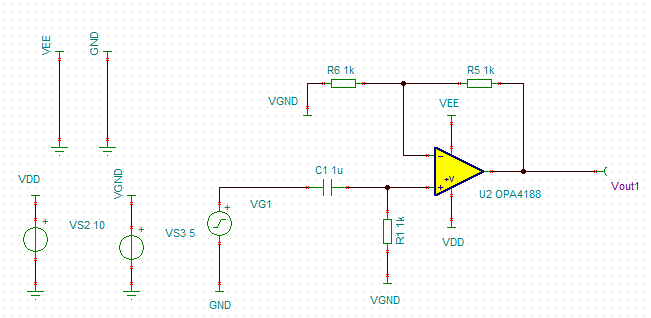
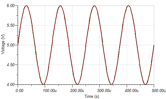
The input is a sine wave of 1.8V peak to peak at 30Khz. Here is the output signal (Vout1 AC coupled) :

As you can see there are distortions on the "falling edge" of the sinus. This distortion depends of the signal frequency and the signal amplitude, it is less visible in lower frequencies but it is still here.

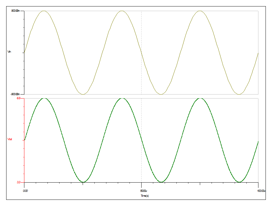
Here is the output (green) plot superposed with the input (blue):

We can see another effect of the distortion : the output doesn't follow correctly the input in the negative side.

The circuit has been designed on a PCB, the power supply is decoupled by a 100nF capacitor and the output is not loaded. As there is no load there is no reasons that make the op amp unstable, I verified and there is no overshoot. I tried with different configuration : dual power supply, simple follower, different resistor values, ... and the problem is still present.

Could it be a measurement problem? I tried to measure Vout1 trough a 1Kohm resistor and the problem is less visible. Still it doesn't make sense that a probe can distort the output at 30Khz. I measured with a PicoScope 3425 and a Tektronics TDS1002 the results are equivalent.

Did someone has already seen this kind of behaviour? Do you have any recommendation?

Regards,

Mickaël

  • Mickaël,

    The circuit you show should work just fine and it does not show any distortion in the simulation - see below. I attached the Tina-TI schematic for your own simulations.

    I assume you use 100nF decoupling cap between VDD and GND.  Since your input signal is referenced to VGND=5V, you must also use a decoupling cap between VGND and GND to prevent VGND drooping.  If this does not fix the problem, please reconfigure the circuit for dual supply as shown below to see if this will fix the problem.

    If this works fine, the next thing to try would be to use dual supply with AC coupling capacitor - see below.

     OPA4188 - autosave 17-03-22 11_16.TSC

  • Thanks for your answer,

    I tried your suggestions but the results are the same. I simplified the circuit to a simple follower with one power supply and a sinus input with an offset of 5V:

    Instead of the OPA4188 I used an OPA188 to avoid potential effect of other channels. The result of the simulation is ok :

    But in practice results are similar to my previous post.

    The 10V is generated by laboratory power supply and the input signal is generated by an arbitrary function generator.

    On one of my board populated by all the components I replaced the OPA4188 by a OPA1654 and every thing works fine.

    Even a simple follower doesn't work with an OPA188. Am I using it wrong?

  • Mickaël,

    Have you added a decoupling cap between the VGND and GND? I cannot see any of the images - in order to upload any of the pictures to this forum, you must use Insert/Edit Media button instead of trying to paste it. 

  • Sorry, I uploaded images by using Insert/Edit Media but I think I wait to long before posting. I will edit my post tomorrow.
    I did add the capacitor between the VGND and GND but it didn't change anything (I tried 100nF and 10uF).
  • Marek,

    I did another follower circuit (schematic from the post : Mar 23, 2017 4:02 PM) with another OPA188 and I have still the distortion near the 30Khz and more, with a sinus wave of +-2V.

    I tried with dual (+10/-10V) and single supply (+10V) with decoupling capacitor between power supplies and ground.

    For single supply configuration the input signal had an offset of 5V.

    Do you have the possibility to test this op amp in this configuration?