This thread has been locked.

If you have a related question, please click the "Ask a related question" button in the top right corner. The newly created question will be automatically linked to this question.

INA195: INA195

Part Number: INA195
Other Parts Discussed in Thread: INA197

:  Hi.

I am using the INA195AIDBVR with a 0.001 shunt resistor to measure current and is powered with 3.3V. I apply 24V to the current resistor. The output I am measuring is 24V and since there is a gain of 100 this would indicate a voltage drop of 0.24V across Rsense. This would suggest a current of 240A which is deffinately not the case as is about 20mA.

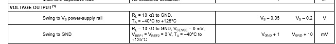
Also from the datasheet the output voltage is:

Analog Output, Out(2) GND ? 0.3 (V+) + 0.3.

so should not go above 3.6V in this case.

Also when I increase the load which causes the current to jump from 20mA to 720mA there is no difference in the output voltage.

What output voltage should I be seeing and how can I correct this?

Thanks.

  • Hi Mark,

    Thank you for posting on the E2E Forums.

    I don't fully understand your statements above. Would you be able to share with us a draft of your schematic, the values obtained at the output of the INA195 and the minimum and maximum thresholds of the circuit currents to be measured?

    I would like to refer you to the datasheet plot on figure 5, Pag 7.

    From the graph above, to keep the error below 1% the measured voltage needs to fall in the range of 40mV or higher, although you may prefer to operate on the more linear region above 150mV, if linearity is important.

    So as a summary, I am able to provide you with some more guidance on selecting the right components for your needs, but before doing so I will require clarification on:

    • How much output error is acceptable
    • Minimum and maximum thresholds of the current to be measured

  • Hi Carlos.

    Thanks for the reply. The schematic used is as follows:

    I have 24V applied to Rsense with a minimal load and I am reading 4.8V on the output. As this unit has a gain of 100 that means a voltage of 48mV accross Vin+ and Vin- and according to the graph would give an error of just under 1% which is acceptable.

    Converting this to a current we have: I = V( Vin+ - Vin-) / Rsense  =  0.048 / 0.001 = 48 Amps. This is definitely not correct, the circuit is pulling less than 100mA so clearly the measurement is wrong.

    I should be reading 2mV on the output for a 20mA current.

    I will be measuring current of up to 60A.

    I hope this explains my issue, if you need any more info please let me know.

    Thanks,

    Mark.

  • Hi Mark,

    Thank you for providing additional information.

    There is something wrong with your circuit. Since the device is powered from a 3.3V supply, then the maximum output cannot go above the supply. There must be something else driving the output to 4.8V

    I would need a complete schematic showing the current paths used. In particular I'm looking for the details below:

    • Are Vin(+) and Vin(-) used on a differential or single ended application?
    • Is the shunt resistor high side or low side?
    • Are the supplies isolated or do they share a common ground?
    • What are both the minimum and maximum currents the circuit is expected to measure.
    • Are the circuit currents bidirectional or unidirectional?

  • Hi Carlos.

    Thanks again for replying. As it turns out for this batch the supplier had provided INA197 devices which have a different footprint to the INA195, and so the voltage applied to Rsense and Vin+ was actually being applied to the output which explains the large voltage on the output. Problem solved.

    Have a nice weekend,

    Mark.

  • Hi Mark,

    Thank you for the update. I'm pleased to know you have found the source of the problem.

    Should you need any further help, please do not hesitate to get back in touch.