This thread has been locked.

If you have a related question, please click the "Ask a related question" button in the top right corner. The newly created question will be automatically linked to this question.

PGA5807A: PGA5807 LTspice simulation model

Part Number: PGA5807A
Other Parts Discussed in Thread: PGA5807

Hello everyone,

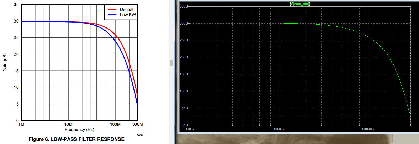
in the last few hours, I tested the LTspice simulation model of the PGA5807.

If I compare the low-pass filter response of the datasheet to the filter response of the simulation, I get a difference of 5 dB at a frequency of 300 MHz (see attached screenshot).

I was informed, that the simulation model was created for the default cut-off frequency of 80 MHz.

Which filter response is more correct? Datasheet or simulation model?

Are there any details to the filter topology, that is used in the PGA5807?

In the attachement you can find the screenshot and the LTspice simulation circuit.

Thank you very much!

Best regards,

Paul Rott

PGA5807_filter_response_LTspice.zip

  • Hi Paul,

    I ran the model in LTSpice as well, and you are correct. The simulation model's frequency response does differ slightly from that of the datasheet at higher frequencies.

    However, the datasheet's filter response is more accurate. This is because an input signal was applied to the ADC input across multiple frequencies, and the output was measured to generate the data on the datasheet.

    The PSpice model is an approximation of the actual device characteristics so, the real-world device frequency response should more closely resemble the response from the datasheet.

    Thanks!

    Sahana

  • Hi Sahana,

    thank you very much for your response.

    Best regards

    Paul