This thread has been locked.

If you have a related question, please click the "Ask a related question" button in the top right corner. The newly created question will be automatically linked to this question.

OPA2348: OPA2348 un-expect output

Part Number: OPA2348
Other Parts Discussed in Thread: OPA2171, OPA2196, OPA2191, OPA2349, OPA348

Dears,

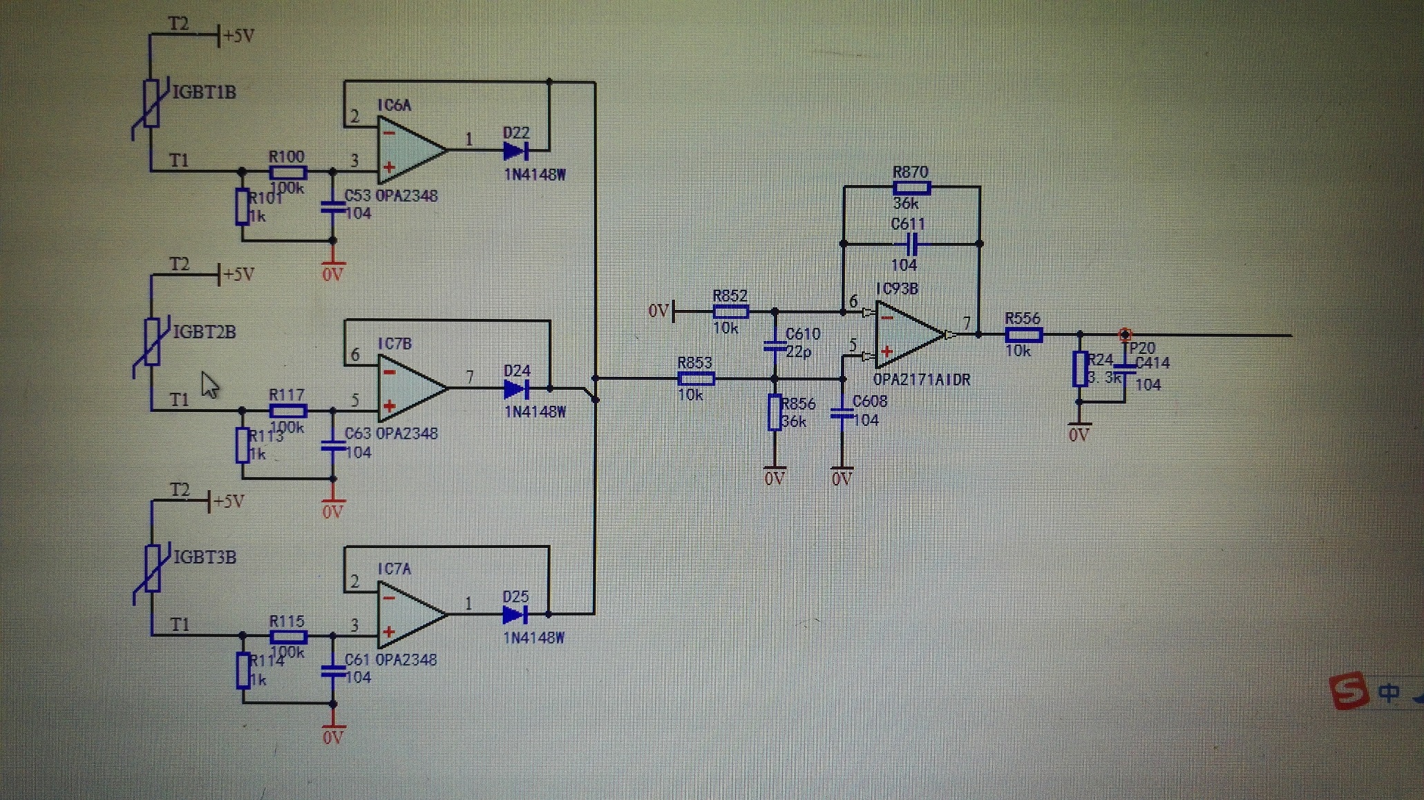
My customer using OPA2348 to monitor the NTC sensor which is integrated on IGBT module. the input voltage of IN+ is range from1.8V~3.7V. the VCC of OPA2348 is +5V.

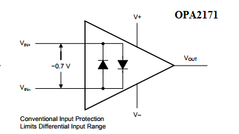
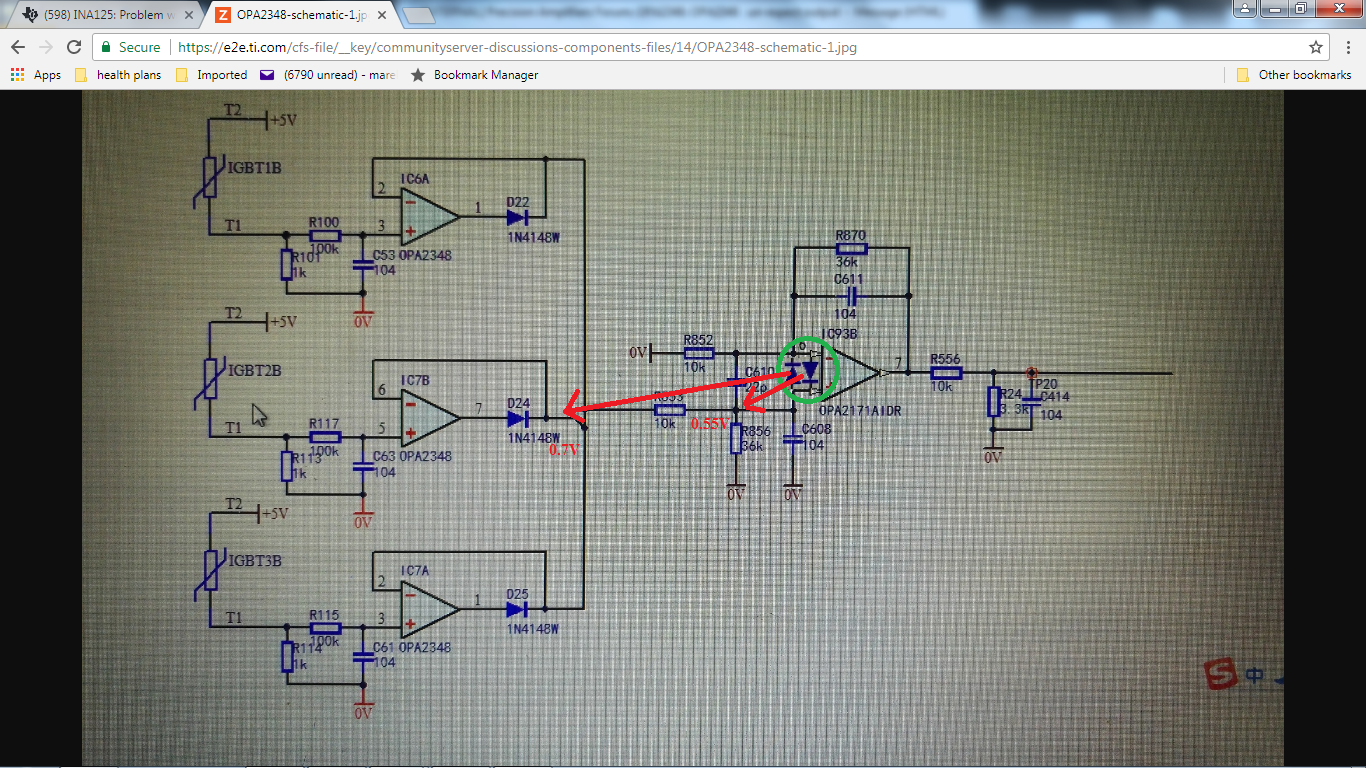
Normally, the IN- (connect to Output via a IN4148) will follow the inputs, but sometimes the IN-(connect to Output via a IN4148) is 0.7V. It may happen when testing for days, sometimes is 10 days. 

is there any risk of using the below schematic? thanks!

  • The full schematic as below:

  • Gavin,

    I believe the problem you see is caused by the back-to-back input protection diodes between the input terminals of OPA2171 - see below.

    In order to eliminate the issue, please use instead OPA2196 or OPA2191, which do not include those input diodes - see below.

  • Gavin,

    Be sure to measure all the device pin voltages to get a complete picture.
  • Hi Marek,
    thanks.
    Is OPA2348 also has the back-to-back input protection diodes? The issue came from OPA2348.

    Another strange thing is that: When OPA2349 enter the "un-expect output status", once we use multi-meter to test the voltage between IN- and GND, OPA2348 will return to normal output within 1 second.
  • Gavin,

    OPA2348 does not have back-to-back input protection diodes but the diodes from OPA2171 still may effect its output-see below.


    With all the capacitance around the inputs, the circuit gets into a lock-up state, which gets reset by discharging the cap with the multi-meter.

  • Hi Marek,
    There is an 10k resister connect the cathode of IN4148 to the IN+ of OPA2171. I am afraid it's very hard to lock-up the voltage of 0.7V at the cathode of IN4148 (also IN- of OPA2348) while the OPA2348 output short circuit current up to ±10mA and the voltage of OPA2348 IN+ is 2.5V around.
    Could you please tell more about it? thanks a lot.
  • Gavin,

    The circuit is called a half-wave recifier because when the output is loaded in a way to require output current sinking, it will only show positive half of the input waveforem - see below.  

    I have simulated the circuit for various values of C1 and the results are shown above. What it means is that depending on R1*C1 time constant, the output will have dramatically different shape, which results in a large differential voltage between the inputs of OPA348 – see above.  The output will eventually snap back to follow the input but for a large values of C1like 100nF, it may limit the frequency below 1kHz (10k||100nF => 1ms).

    OPA348 Gavin.TSC