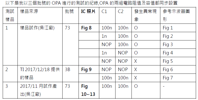
This thread has been locked.

If you have a related question, please click the "Ask a related question" button in the top right corner. The newly created question will be automatically linked to this question.

LM258: Why some LM258 output short current will increase until the ic damage

Part Number: LM258

Hi,

Our customer found that all the channel 2 of LM258 IC they got can't operate normally in the short current test.

But the sample I requested from BU can pass the short current test.

Below is the top view symbol (which will fail in short current test)

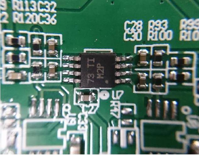
Below is the top view symbol (which won't failed in the short current test)

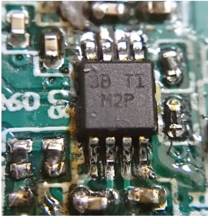
Here's the test condition

IC which failed in short current test:

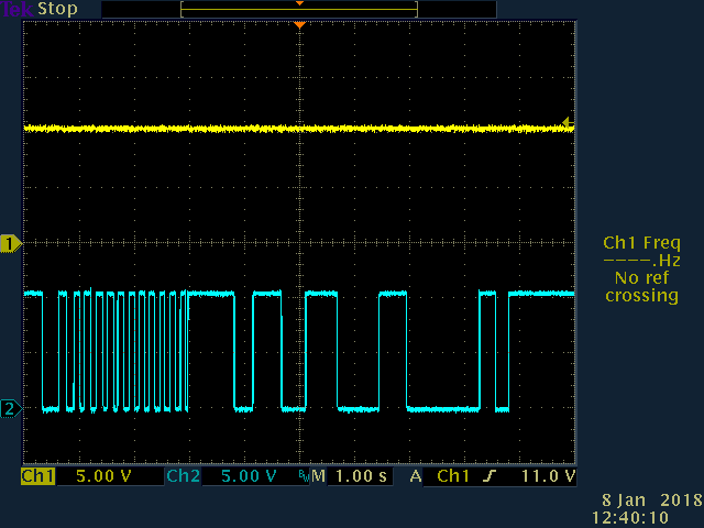
When the feedback cap C1=0 and output cap C2=100n

All the IC will operate normally like the figure below in the test.


But when we adjust the the capacitance of C1 from 0 to 100n.

we can found that when we short the channel 2 to ground

 The LM258 finally damaged and the figure looked like the figure below.

w

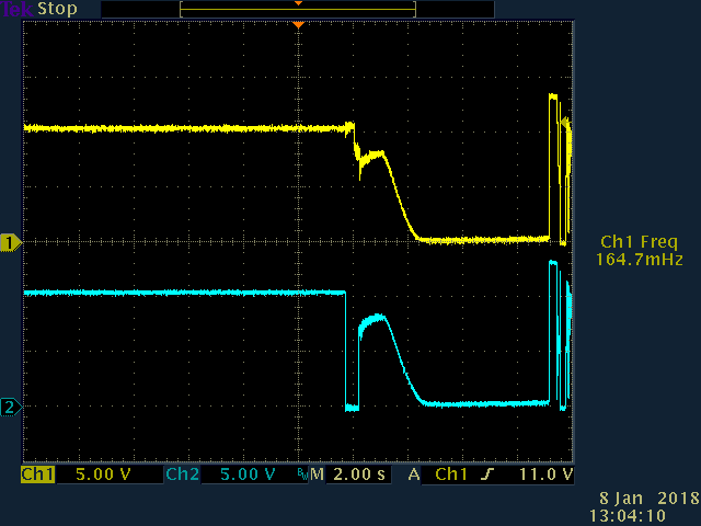
Could someone please explain that why this waveform in our test?

Thank you 

Best Regards,

Willy Chen

  • Willy,

    Is the yellow signal one output and the blue signal the other output that is shorted (and release) by hand?
  • The blue one(channel 2 output) was shorted and release by hand

    and the yellow one is the channel 1 output of LM258 

    THANK YOU

  • Willy,

    When you short the output without the 100nF feedback capacitor. The output will current limit and will protect itself. So no damage.

    When the capacitor is present a second effect happens at the time of output short. The capacitor is charged to 9.1V before the short. At the moment of the short the output goes to 0V, therefore the inverting input will try to go to -9.1V. There is a diode from input to ground, therefore the capacitor will discharge very quickly at high current. This input diode current also turns on parasitic transistors that cause new current flows inside the device.

    Normal latch up testing only tests to -100mA. The capacitor peak current is likely much higher. Also latch up test and short output tests won't be tested at the same time.

    Try adding a 91 ohm or higher resistor in series with the 100nF capacitor and try the short test again.

    I will also try this test.

  • Hi Ronald,

    Thanks a lot for your explanation.

    We did a test adding a 91ohm series resistor with 100nF, this issue can be fixed. But there are two questions from customer.

    1. Why this issue happened at some lot number devices but some didn't(the samples from eStore don't have this issue, it is verified by field side and customer)?

    2. You can find below table, when C1 was empty and C2 was placed a 100nF cap., RD still can duplicated the abnormal phenomenon. Do you have any comment on this test?

    Thanks a lot

    Vincent Chen

  • Vincent,

    1) There is no meaningful difference between 73 and 3B build instructions. However, 2 silicon dies are qualified for LM258DGKR on both dates. This might be the difference.

    2) C1 empty will not stress input pin. C2 present (especially if the test setup was a breadboard and not a well laid out PCB design) could react with circuit inductance creating large voltage transients.
  • Hi Ronald,

    Thank you for the reply.

    2) C1 empty will not stress input pin. C2 present (especially if the test setup was a breadboard and not a well laid out PCB design) could react with circuit inductance creating large voltage transients.
    --> Customer test it on the PCB board, just solder two wires from OUT pin and ground and connect them repeatedly. Maybe it could cause large voltage transients, so you think that will cause this kind of phenomenon? If placing a small value resistor on R3 or in series with C2 can help to solve this issue?
    Please let me know if you have any comment can help to fix this issue.

    Best Regards,
    Vincent Chen
  • Vincent,

    Increasing R3 is a good way to reduce stress on both the output and the inverting input pin. It also has the benefit of already having a place on the PCB.
  • Hi Ronald,

    Got it, I will let customer try it.

    Many thanks~
    Vincent Chen