This thread has been locked.

If you have a related question, please click the "Ask a related question" button in the top right corner. The newly created question will be automatically linked to this question.

LMC6082: as ph electrode amplifier

Part Number: LMC6082
Other Parts Discussed in Thread: TINA-TI, , LMC662, LMP7721, OPA376, OPA191, OPA197, LMC6482

Dear Sir/Madam, 

I am working on pH electrode amplifier . Planning to use one of the op-amps "LMC6082C" or LMC662C or LMC6482 which have fA input bias current. Attached circuits and simulated results using Op-amps "LMC6082C" and "LMC662C" in TIna-TI. 

LMC6082C is giving delta value between 1.8mV to 5mV for pH glass electrode source resistance 50M to 500M ohms. 

LMC662C is giving delta value between 6m to 9mV for pH glass electrode source resistance 50M to 500M ohms.

In case of LMC662  input bias current of 2fA (High compared to LMC6082) , still delta is more (6m to 9mV). In case of  LMC6082 input bias current of 10fA ,  delta is less(1.8mV to 5mV).

Please give your valuable comment. 

1. Also give comment on schematic , is it better to go for proto design. Any comoponents yet to add???

2. Also which opamps is better to go for proto design. 

Thanks

Srinivas 

pH sensor_signal_conditioning.xlsx

  • Hello Srinivas,

    Since you are comparing calculated and simulation results for the LMC6082 and LMC662 keep in mind that the simulated results are affected by the bias current, bias current offset, and voltage offset are established within the models. Therefore, just as with real devices, the results may be a little different than the calculated.

    1. Also give comment on schematic, is it better to go for proto design. Any components yet to add???

    • The tolerances of the passive components will directly affect the circuits accuracy
    • The higher the value of resistance R1 is made, the higher the resistor noise will be, √(4kTR1B).
    • The op amp current noise will be converted to voltage noise when it flows through R1. Using the lowest R1 resistance will reduce this type of noise.
    • Observe the information provided on Pg. 11 of the LMC6082 datasheet, and Pg. 9 of the LMC662 datasheet, PRINTED-CIRCUIT-BOARD LAYOUT FOR HIGH-IMPEDANCE WORK.
    • Add power supply decoupling capacitors from the op amp V+ pin to ground.
    • Use water soluble flux to solder components. Then, ultrasonic clean the boards with DI water after all soldering has been completed. It is best to employ two clean cycles.

    2. Also which opamps is better to go for proto design? Here are some others to consider:

    • LMP7721
    • OPA376
    • OPA191
    • OPA197

    I hope this helps.

    Regards, Thomas

    Precision Amplifiers Applications Engineering

  • Hello Thomas, 

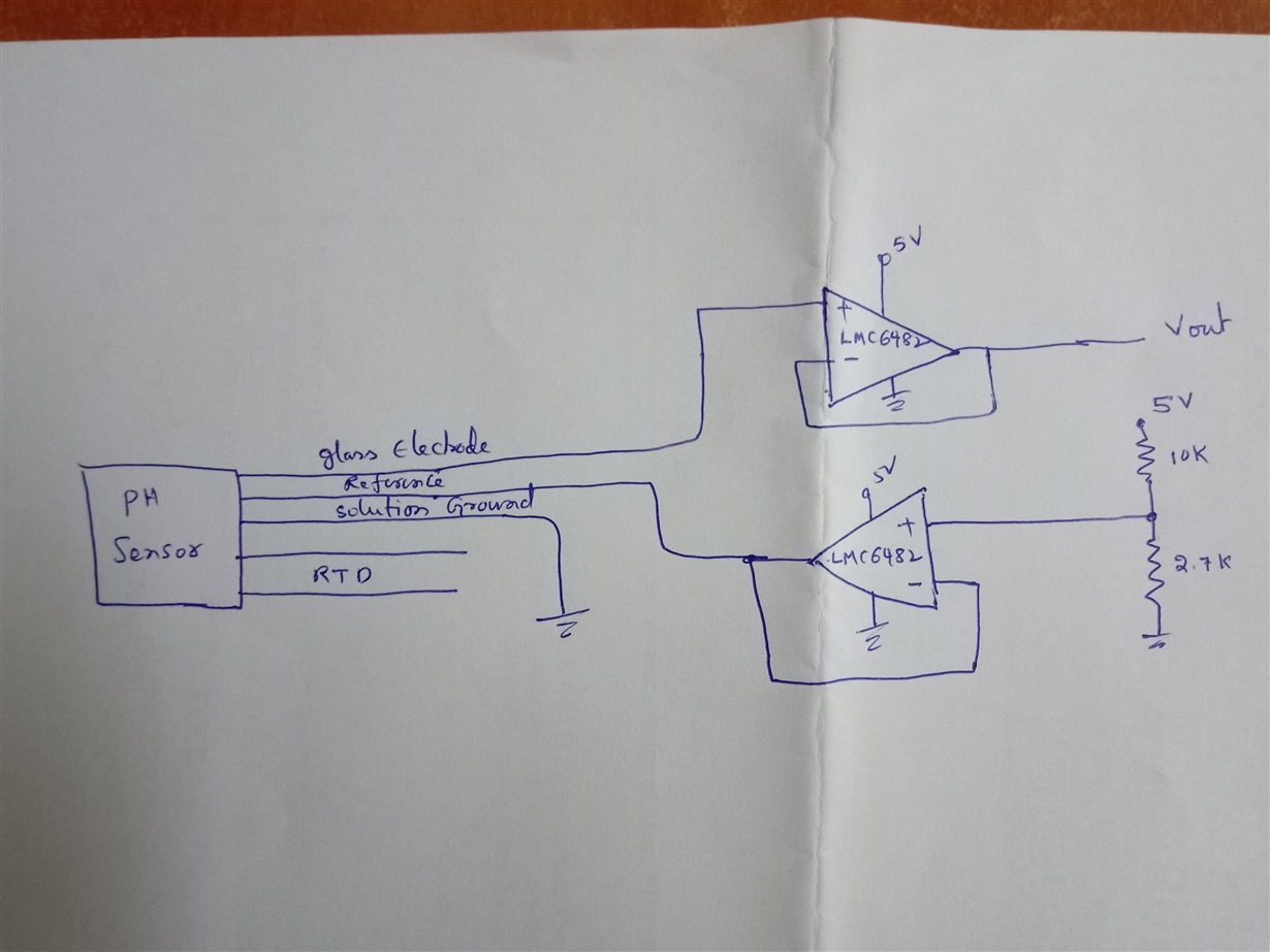
    THis is regarding pH sensor . Attached the schematic here. It is not working properly. Let me know your comments what is going wrong. 

  • Hi Srinivas,

    I just simulated with TINA-TI the LMC6482 with a biased 500MR resistance at the input, just like in your circuit. The simulation showed me an input bias current of about 5pA. If you have a look into the datasheet you will notice, that this is the specified "maximum input bias current". But take care, the specified "typical input bias current" is only 0.02pA. This will give you a Delta of only 10µV!

    So, what you see is just a simulation effect, but not the performance of a typical LMC6482!

    Kai

  • As per attached schematic , I made circuit . When I dip sensor in pH 4 and 7 solutions , I am getting same output voltage. There is no changes
  • There are three terminals except 2 Rtd terminals. 1 glass electrode , 2 ref electrode 3 solution ground. Solution is connected ground . 0.95v connected to Ref electrode. From glass electrode I took output and connected to lmc6482. Is it right. Something wrong
  • Hi Srinivas,

    are we talking about a differential ph sensor?

    Kai
  • Hi Srinivas,

    Are you using TI's AN-1852, Designing with pH Electrodes, Application Report? If not, please find it here for more information:

    How does the circuit behave?

    How is your circuit constructed?

    What precautions did you take to make sure that the PC board and components are ultra-clean and free of contamination?

    Regards, Thomas

    Precision Amplifiers Applications Engineering

  • Srinivas
    We haven't heard back from you so we assume this resolved your issue. If not, just post again below (or create a new thread if this one has timed-out)

    thanks
    Dennis