This thread has been locked.

If you have a related question, please click the "Ask a related question" button in the top right corner. The newly created question will be automatically linked to this question.

LMP7731: Failing units on current sensing application

Part Number: LMP7731

I am having some issues with this amplifier.

Application: shunt voltage (low resistance 0.05Ohms) differential input amplifier with gain=8. The schematics can be shared if needed.

Symptoms on failing unit:

-              Random or permanent failure on final application

-              Gain variations are observed

-              Input currents are 1000 times bigger than expected by datasheet on IN+

-              Thermal analysis shows temperature variation during failures

-              Power supplies on application (+2.5VDC, -2.5VDC) have been verified

-              During failure mode, I observe power supply consumption variation.

-              One fail component shows a non-linear response (almost constant output) for low input voltages in linear non-inverting configuration. It was compared with a new brand component.


Thanks for your support

Roberto

  • Roberto
    Please send us your schematic and one of our team will assist you.
  • Hi Denis,

    You will find hereafter the schematics.

    Best regards,

    Roberto

    Présentation_iac.pdf

  • Hi Roberto,

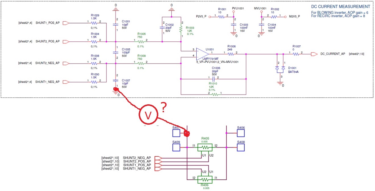
    how are the shunts (S406...S409) connected to the LMP7731 circuit? Or by other words, what voltage do you measure between S407 and GND of LMP7731 circuit?

    Kai
  • Hi,

    Shunts R405 and R405 are soldered on the same PCB.
    Electrical curres going thru the shunts are from 0 to 20 Amps. Voltage goes then from 0 to 50mV

    Best regards

    Roberto
  • It is NOT enough to apply a differential voltage between the input terminals - input voltages must also be referenced to system ground or they will collapse on one of its rails. Thus, you may NOT float the inputs - please provide for the input current path to the system ground while making sure that you do not violate the input common-mode voltage range.
  • Hi

    Would C409 & C410 on the following schematics be enough to avoid the collapse on rail?

    I will verify input CMVR.

    Thanks

    0602.Présentation_iac.pdf

  • Hi Roberto,

    no. You must guarantee, that the shunts' voltages are within the power supply voltages of LMP7731. One solution could be to connect S407 to the 0V of your LMP7731 circuit, if your appliction would allow this.

    Kai

  • Hi Kai,

    I forgot the "GRAIN_CAFE" on the schematics that connects one input (S402, S404, S406 & S408) to ground.

    Thanks
    Roberto
  • Hi,

    The component was analyzed by an external lab that found a lifted bonding on negative input.

    Best regards,

    Roberto

  • Hi,

    Do you know how can I share the FA report with TI team for a feedback?

    We are investigating on other components that could be send back to TI for analysis.

    Best regards,

    Roberto

  • Hi Roberto,

    There is a reasonable probability that the LMP7731 is being damaged by an unanticipated electrical over stress (EOS) event occuring in the system. Would it be possible for you to instrument the current shunt circuit with some DSO probes? The idea is to power the application circuit and run it through it various operating cycles from power ON, to power OFF, looking for unexpected high-voltage occurances.

    The DSO probes (10x) would be connected to the shunt through which the high current flows, the inputs of the LMP7731, and its power supply pins. The goal is to see if an unexpected high-voltage transients occur somewhere in the circuit; sometime during the operating cycles.

    The schematic you provided doesn't show any protection devices such as transient voltage suppressor diodes (TVS) being used in the circuit. Therefore, there is little in the circuit to protect the LMP7731 from an EOS event should one occur.

    Regards, Thomas
    Precision Amplifiers Applications Engineering
  • Hi Thomas,

    Thanks for your support.

    Design team is analyzing validation data to verify if any EOS is possible, we will eventually make new measurements as proposed. Do you know the voltage level that could lead to this kind of damage? Shouldn’t we see other damages on the IC?

    In addition, the lab report indicates the presence of Kinkerdall voids and purple plague that are normally more related to the manufacturing process.

     Best regards,

    Roberto

  • Hello Roberto,

    The LMP7731 is a low-voltage op amp with an absolute maximum supply voltage rating of 6 V, and maximum input differential voltage of +/-2 V. Beyond those specified maximums no other limits are listed in the datasheet. Very likely the LMP7731 wouldn't survive any application of a voltage applied to an input, or the output that exceeded the supply voltages. If the LMP7731 has been subjected to an EOS event and has been damaged, then there should be damage to the die in the circuits where the EOS was applied. The FA report you mention should have identified damaged die areas if the analysis had gone that deep.

    Be sure that you obtained the LMP7731 devices from an authorized TI distributor before taking the following action. TI needs to know that the devices are genuine TI product:

    Kirkindall voiding is a very unusual occurance in TI semiconductors because of the very extensive material evaluations and processes that we use to assure its prevention. If indeed this is occuring, then I suggest you work with your authorized TI distibutor from whom you obtained the LMP7731 devices and request that they initiate a TI Failure Analysis (FA). The distributor can provide you a Failure Request form which you will need to fill out completely. The form provides how the returns are to be prepared and where to ship them for the FA. Do include your externally prepared FA report with your TI FA request form.

    Regards, Thomas

    Precision Amplifiers Applications Engineering

  • Thank you Thomas,

    We will contact the distributor.

    Best regards,
    Roberto