This thread has been locked.

If you have a related question, please click the "Ask a related question" button in the top right corner. The newly created question will be automatically linked to this question.

XTR106

Other Parts Discussed in Thread: XTR106, XTR115, XTR111

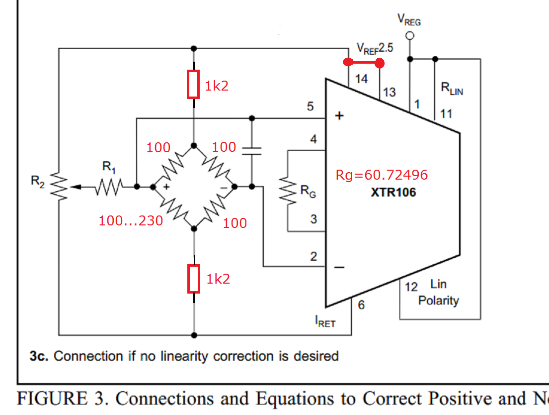
I am going to design  4 mA to 20 mA transmitter using XTR106... can u help me for design... this is new to me....I want to use whetstone bridge with XTR106 from datasheet i get to know bridge impedance is very important for desiging 4 mA to 20 20 mA transmitter circuit.I am using  whetstone bridge in that one arm resistance get vary from 100 E to 230 E. 

1)I didn't clear term bridge  impedance 

2)Also not understand Vtrim term

  • Hi Amruta,

    the bridge impedance is the impedance seen between the two excitation points. If all four arms are identical, then the impedance of the bridge is equal to the resistance of one arm. An example: If all four arms have an resistance of 350R, then the brigde impedance is 350R. Or by other words, this is a 350R bridge.

    The Vtrim is not urgently needed to make the circuit work. But it helps to improve the accuracy of the circuit. Have a look at figure 1 of datasheet. Assume the bridge is not perfect and shows some unsymmetry in idle state. Or assume that there is a non vanishing input offset voltage of XTR106, then you can correct this by the help of R1 and R2. With these two resistors a small current can be injected into the bridge. With this intended imbalance you can correct the imbalance caused by the non ideal bridge and non ideal XTR106. You need to adjust R2 until the output voltage becomes zero.

    Kai
  • Hi,

    Thank you so much for quick reply now i understand bridge impedance term but still i have doubt about one term in datasheet that is B is the non linearity relative to Vfs. Also in application I will use one arm resistance of whetstone bridge vary from 100E to 230E and i want change in current 4 to 20 mA linearly.

    Thank you.

  • Hi Amruta,

    linearity correction is only useful for bridges which are well known for their nonlinearity. Maybe you don't need the linearity correction at all.

    Kai
  • ok..thank you..if i will not consider linearity then can i take value of B 0.5% or it will be different value for not considering non linerity .
  • Hi Amruta,

    how much linearity you will have only depends on your bridge. As long as I don't know what bridge you use I cannot say how much linearity you will have and if you have to correct it with the linearization feature of XTR106 at all. :-)

    Kai
  • Amruta

    We haven't heard back from you so we assume this resolved your issue. If not, post a reply below, or create a new thread if this one has timed-out.

    Thanks
    Dennis
  • hello,

    still i am not clear with wheastone bridge combination.I have use bridge in which one arm resistance change from 100e to 230e..i dont understand from datasheet how much differntial volatge need to xtr106 and in xtr115 part article i had read that bridge current should be less than 1A so this will be applicable for xtr106 also..also one more thing i wont use preamplifier so what should be the differential output from wheastone bridge..In datasheet mentation common mode voltage should be 1.1v to 3.5v..for my application can i take it as when wheastone bridge balance output of wheastone bridge should be minimum 1.1v.

    I dont clear all above thing..please give me suggestion

    Thank you..

  • I want to correct that in xtr115 part article i had read bridge currnet should be less than 1ma
  • Hi Amruta,

    if you want to take the XTR106, then you can make it in this way:

    The two additional 1k2 resistors limit the bridge current to about 1mA. With the connection between pin13 and pin14 the 2.5V reference voltage is chosen. Pin1, pin11 and pin12 are configured for no linearity correction. To make the output current swing from 4mA to 20mA when one of the bridge resistors shifts from 100R to 230R a calculated gain setting resistor of RG = 60.72496R is needed.

    Kai

  • thank you so much for reference design but in datasheet for non linearity use bridge excitation volatage 5v..
  • Hi Amruta,

    this has nothing to do with it. It's only an example. Linearization is turned-off for 2.5V and 5V.

    Kai
  • Hi kai,

    Thank you so much for valuable guidence I had done with 100e to 230e change in resistance and curent change.For 100e  output current is 4.1mA and 230e output current is 21.8mA.Now I want to adjust zero and span.In datasheet mentation for zero adjustment but nothing about span adjustment.

  • Hi Amruta,

    span adjustment is done by correcting Rg.

    Kai
  • Hi kai,

    Done with zero and span also thank you.

    also i 2nd thing now i want to convert PWM voltage to current.I will go through xtr111 and xtr115.which one correct for my application.