This thread has been locked.

If you have a related question, please click the "Ask a related question" button in the top right corner. The newly created question will be automatically linked to this question.

TLE2142: Latch-up

Part Number: TLE2142
Other Parts Discussed in Thread: TLE2141, TPS60400

Hello,

Our customer use the TLE2142, have a latch-up issue.

The customer use the TLE2142 with dual supply voltage. There is an unused circuit, the customer make a

voltage follower circuit with +input connect GND.

They shut down the negative supply voltage before the positive supply voltage power down. 

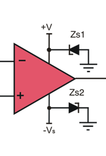
Then it occur latch-up. The rush current flow through the VCC+ to +input of the unused circuit.

I thought a latch-up model. Is my understanding correct?

Latch_up.pptx

The customer will add a resistor between +input and GND.

Is it a workaround for latch-up?

Best Regards,

Naoki Aoyama

  • Hi Naoki,

    only if the input voltage can become more negative than the voltage at the negative supply pin problems can occur. So, maybe the other OPAmp in the TLE2142 is the problem?

    Can you show a schematic of the whole TLE2141 circuit?

    Kai
  • Aoyama-san,

    Indeed the behavior you are describing is that of a parasitic latch being formed when the TLE2142 supplies are turned off at different times. I have observed this kind of behavior with other op amps when the supplies are turned on at different times. This tends to be more common with older op amps because the CAD checks for latch structures were not as sophisticated when they were created as they are today.

    Latches, which are often 4-layer semiconductor structures like SCRs, can sometimes be prevented from forming by limiting the current that can flow through a parasitic current path. If a particular current threshold is not reached the latch doesn't form and the current remains too low for the latch to form. I have found, and as you have suggested, that adding a high resistance in series with an input limits the current to the point where the latch can't form when the input circuit is invloved in the latch formation.

    Kai's point needs to be considered as well. There is the possibility that it too might be latching. If there are resistances used in conjunction with its inputs, they may prevent the input current from rising high enough to form a latch. But just make sure that section of the TLE2142 isn't latching too.

    Regards, Thomas
    Precision Amplifiers Applications Engineering
  • Hello Kai, Hello Thomas,

    Thank you for your reply.

    The customer don't disclose the circuit in detail. But  I got a rough circuit.

    I attach it.

    circuit_information.pdf

    The issue has occurred in 6 out of 16 devices. All 6 devices are same symptoms.

    That is, Pin 5, Pin 7 and Pin 8 burned out. The used circuit does not burn out.

    (The Pin 7 is also burning, but it is beside Pin 8, so it may have burned.)

    The power sequence of the customer as follows.

     Power on the Vin=3.3V.

    Power on the VCC+ = 37V.

    Power down the Vin=3.3V.

    then burned out.

    Best Regards,

    Naoki Aoyama

  • Hi Naoki,

    a Schottky diode could be added to the output of TPS60400, like shown in figure 21 of datasheet. This would make the clamping more robust and would decrease the voltage drop across the Schottky diode. This measure will protect both OPAmps in the TLE2142.

    Then I would insert a resistance of about 1k in series to the input of the left OPAmp.

    For the right OPAmp, the "unsed circuit", I would use a different scheme: Take a voltage divider from the positive supply to GND and generate a positive voltage of 3V...4V. Connect pin 5 of TLE2142 to this potential.

    Kai

  • Hi Kai,

    Thank you for your suggestion.

    At last, I summarize the causes and the workaround of this issue as follows.
    ----causes-----
    Is the mechanism of the issue consistent with the figure of the attached file before (Latch_up.pptx) ?

    ---workaround---
    1. If possible, power down VCC+ before power down VCC-
    2.Take a voltage divider from the positive supply to GND and generate a positive voltage of 3V...4V.
    Connect pin 5 of TLE2142 to this potential.

    Do you have any other advice?

    Best Regards,
    Naoki Aoyama
  • Hi Naoki,

    Thomas tried to explain that a parasitic thyristor is formed inside the chip which can be fired by a certain current flowing into the chip's substrate:

    en.wikipedia.org/.../Silicon_controlled_rectifier

    en.wikipedia.org/.../Latch-up

    Yes, add a Schottky diode to the output of TPS60400, like shown in figure 21 of datasheet. This would make the clamping more robust and would decrease the unwanted positive (!) voltage at the output of TPS60400 during power-on and power-off.

    Kai

  • Hi Kai,

    Thank you for your advice.
    As a reliable workaround, I will suggest the customer to add a Schottky diode, too.

    Very Thanks,
    Naoki Aoyama
  • Hi Aoyama,

    In addition to Kai's recommendations we always recommend adding transient voltage suppresser diodes (TVS), or zener diodes, to the op amp supply lines when there is any risk of the two supplies coming up at different times. The diodes make sure that there is always a current path to ground from the otherwise floating supply pin.This helps reduce the likelihood of a latch condition being created.

    Regards, Thomas

  • Hello Thomas,

    Thank you for your advice.
    I will suggest the customer this recommendation, too.

    Thanks,
    Naoki Aoyama