This thread has been locked.

If you have a related question, please click the "Ask a related question" button in the top right corner. The newly created question will be automatically linked to this question.

INA168: Bidirectional Current monitor with INA168 - Shunt Suggestion

Part Number: INA168
Other Parts Discussed in Thread: INA170

Hi ,  

I am testing the INA168 device in my lab bench  so i can use it in an application that i am working on for current monitoring of a load powered from a battery.

At the moment the only practical tests that i have done on the breadboard is to check  the output of the INA168 in relation with the input voltage. The calculations are correct and the resistor that defines the  gain works as expected. For example,  using 11.7mV Input voltage (Voltage across Rshunt) i get 220.3mV on the Output using a 100K Rload resistor which i think is quite good and expected gain of 20.

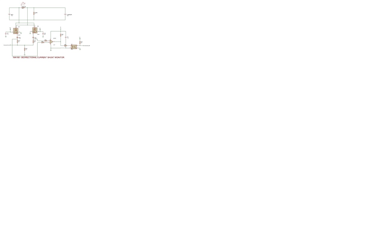
Now lets come to the point. For the project i am working with, i have to measure a bidirectional current using a shunt resistor. The circuit configuration that i want to use is shown below.

I need some information about how i can choose the ideal resistance for shunt so the output voltage across the shunt will be within the allowable voltage of the INA168. Which means that the voltage across the Rshunt must be between 60mV  to 500mV . 

For this project i need to measure a current range from 0 to 60A maximum. 

What shunt resistor i need to choose so i can be able to use the circuit configuration as shown below?

Thank you in advance 

Regards

George

  • Hi George,

    The maximum recommended differential input for the INA168 is 500mV, so for a max current of 60A an Rshunt value of 8mOhm will be fine.


    Regards,
    Manuel Chavez
  • Hi, i am trying to use the INA168 as i already told connected to the circuit attached previously.

    I have got a few INA168  devices smoked.. I can't find the reason that one of the devices (U2 on the schematic) is getting hot and finally burned.

    Any help is welcome since it is the first time that  i am dealing with this device and i still can not figure out how to have it properly working.

    Thanks in advance

    George

  • George,

    The INA168 is a current-output current shunt monitor. This device is unique because of its current-output characteristic, and it will not be damaged if the voltage on the Vin+ pin is lower than on the Vin- pin (state of one INA168 at any given time).

    U2 is the active INA168 when the battery is being charged, correct? The device heating and eventually smoking is a sign of max operating conditions being exceeded. I have the following questions: How do the system and device behave from power up to device failure? What is VDD connected to? Is the battery's ground separate from the system?

    I will await your response.

    Thank you,
    Manuel Chavez
  • Hi Manuel and thank you for your time and your help!

    Yes the U2 is active when the battery is being charged, correct.  

    Both devices power supply pin(VDD) is connected to +5V.

    The battery's ground is NOT separate from the INA168 ground.

    The failure of the device comes unexpectedly a few seconds after i power up the board. I just see a little smoke coming out of the chip.

    I am trying to figure out what is wrong but i am still have found nothing.

    Thanks again!

    George

  • You're welcome, George!

    Is the battery charging or discharging at the time mentioned above?


    Thank you,
    Manuel Chavez

  • The charger was not connected at this time and the battery was discharging while the U2  get smoked.

    I have made a simulation circuit using Proteus ISIS and the results was as expected.....correct.

    Regards

    George

  • Hi George,

    Sorry for taking long to reply. The schematic on your original post seems operational for the device although component values are blurry. Can you reply with a clearer screen capture of the simulation circuit?

    The devices may be damaged from a hardware error. To determine whether it is an input or output fault:

    Input: Disconnect the Vin+ and Vin- pins (3 & 4) and power the system.
    Output: Disconnect the D17 diode or pin 1 of the INA168 to open the output branch of the circuit. Operate the rest of the system normally.

    To begin testing, you may disconnect all three pins and reconnect the output then input. Observe which connection causes U2 to overheat and smoke.


    Respectfully,
    Manuel Chavez
  • Hi George,

    How is testing with this system going? If you are willing to consider a single-device solution, the INA170 is bipolar and functionally similar to the INA168. One of these can measure current in two directions with the usage of a reference pin.

    It is an involved change, but didoes would not be necessary and sign can be determined based on the reference output level. These two devices have similar specifications as shown in the following image, and the INA170 can be optimized for your system.

    Let me know how the project is going and if this is something you would like to pursue. Thank you!


    Best,
    Manuel Chavez

  • Hi Manuel, thank you for your interest and your time. 

    The INA170 looks ideal for my project and i will order a few devilces to start making test in the lab. 

    The overall process of the project is going well.

    Regarding the INA168, i will manage to get it working properly and i will definitely use this device in my future projects to measure current!

    Best Regards

    Georgios Bardakis 

  • Georgios,

    I'm glad to hear that! Feel free to follow up on this post or create new threads throughout your project. We are ready to help.

    Thank you for using TI parts,
    Manuel Chavez