This thread has been locked.

If you have a related question, please click the "Ask a related question" button in the top right corner. The newly created question will be automatically linked to this question.

LM8261: LM8261 and noise

Part Number: LM8261

Hi,

 I’m using a LM8261 (IC20) in a circuit (see picture attached) that makes the function of an electronic inductor.

At the end of the circuit after C193 there is an ADC and a µC. The signal processing found some noise around 1 kHz in 2-3% of the production. See pdf file attached before and after replacement ICNoiseBeforeRepalcement.pdfNoiseAfterreplacement.pdf.

I have found that the noise is originating in the IC20 area and if I replace IC20 with a LM8261 that I have in the lab the problem is solved. See pdf.

I did this operation on some boards and the replacement works always better.

I don’t know the reason of that behavior, and I suppose that the LM8261 used in the production are of good quality.

So could be the circuit? I know that there is 1M ohm resistor that produce 7µV of noise but I have to use that value.

Do you see any issue in the circuit?

LM8261 is a good device, but could I improve or solve that noise problem using a different OpAmp?

Best regards

Davide

  • Hi Davide,

    It looks like you tried to attach an image of your schematic but it didn't post correctly, can you try again?

    Just so I fully understand your question - are you saying that both the good and bad circuits use the LM8261 and some copies of the LM8261 work better than others?

    We have a number of lower noise density op-amps (<10nV/rtHz), which you can find in this list: www.ti.com/.../products.html

    Best,
    Paul
  • Attached the schematic.

    Yes correct, there are LM8261 that work well and a small percentage not. Why?

    Am I using the IC near the limit of some characteristic?

    Best regards

    Davide

    Schematic.docx

  • Hi Davide,

    Thanks for the schematic and information. I have a couple questions that I'm hoping you can answer that will assist us in answering your question.

    * In your first post, you mentioned that swapping IC20 reduced the noise. On the schematic, IC20 is an MC33074 and IC28 is an LM8261 - did you mean to say that when you swap IC28 that the noise goes down? Or are you truly swapping the MC33074 for an LM8261?

    * What is your input signal into the non-inverting node of IC20 through C126? If you can provide input amplitude and frequency, that would be helpful.

    * Is C138 a capacitor or does that symbol denote some other kind of component (I haven't seen such a symbol before).

    * Can you provide scope shots of the signals at C193 and the collector of Q16 (voltage and current would be useful here).

    * Any additional information you can provide on your application would be helpful. The simulated inductor is a circuit we don't see very often.

    Best,

    Paul

  • Hi Paul,

    sorry for the confusion.
    The component involved with the noise is only IC28. In all the boards that have the noise problem when I replace IC28 with the same part number LM8261 the noise disappear.
    That test is done without any signal applied and in stationary condition.
    So C126 is biased with a DC voltage.
    C138 is a capacitor and that strange symbol is because isn't mounted on PCB.
    I'll provide additional info ASAP.

    Regards
    Davide
  • Hi Davide,

    We simulated the op-amp inductor circuit and found that it is marginally stable, it only has a few degrees of phase margin. Perhaps the failures that you're seeing are stability issues and not really noise.

    If you still have some of the misbehaving units around, can you try changing R77 to a higher value, like 20Ω and then re-run the noise analysis? That seems to improve the stability quite a bit.

    Best,

    Paul

    gyrator.TSC

  • Davide,

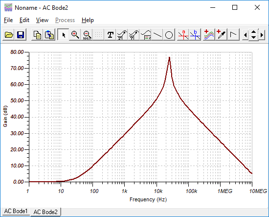
    In addition to stability consern, the noise gain of a gyrator is high.

    Noise Gain chart; output noise will be op amp input noise multiplied by this gain. (ROUT = 1 ohm)

  • Hi all,

    I replaced that resistor and tested two board without good results. In only one board there was an improvement but not enough.

    At the moment I have only two boards with the problem and I would test this solution on more samples.

    In the active inductor R77 is the series resistor of the inductor that I would make and I can’t use an inductor with 20 ohm series.

    In the gyrator.TSC file attached R2 is 10k but in my schematic the impedance is different (10µF +49.9 ohm). Probably the results would be different.

    I’m not an user of TINA I downloaded today to see the schematic so is better that you perform the simulation.

    I’m interested on the noise the gyrator simulation that you posted. How did you get it?


    Regards

    Davide

  • Davide,

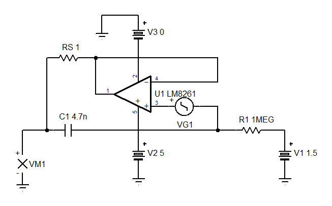
    My noise gain test circuit. VG1 is input voltage source [op amp noise]. VM1 is output.


    gyrator(noise gain).TSC

  • Thanks Ron I'll do some simulation.