This thread has been locked.

If you have a related question, please click the "Ask a related question" button in the top right corner. The newly created question will be automatically linked to this question.

LMH6553: Recovery from clamped square wave shows a slow decay

Part Number: LMH6553

Hello,

We are using the LMH6553 to drive the input to an ISL214S50 ADC and clamp the signal so that the ADC input is not over-driven:

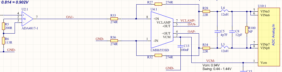
VCLAMP is derived from a DAC081C081CIMK with 500R output and 100nF decoupling next to the LMH6553 VCLAMP pin. VCM = 0.94V so the LMH6553 will swing between 0.44V and 1.44V with a 1Vpp input.

The scaling in our system gives an 8V reading when the ADA4817 output is 1V.

I have observed an unusual recovery from a square wave as the clamp level is reduced.

The following display shows the response to an 875mV (=7V on display) unipolar 5kHz square wave as the VCLAMP level is reduced from 1500mV to 1100mV. The high levels are to the left and right of the display and the centre region is the zero level of the pulse. This is what I would expect, so all OK.

But then I zoom on the zero level and see this:

There is an "undershoot" on the step down to zero with a decay time constant of about 9us. As VCLAMP is reduced from 1500mV to 1100mV the undershoot gets bigger, being about 70mV with VCLAMP at 1100mV. 70mV on the display would correspond to about 9mV on the LMH6553 output.

I checked VCLAMP and is it stable, no ripple or transients.

So is it possible that the clamping in the LH6553 can have this recovery from an overload? and get worse as the clamp level gets closer to VCM?

The data sheet spec's overload recovery time as 600ps, so not sure what I am seeing here. Any help much appreciated!

Thanks, Ken

  • Hi Ken,

    what are the supply voltages of LMH6553?

    Please have a look at figure 60 of datasheet to see how the "Clamp Overdrive Recovery Time" is defined.

    Kai

  • Hi Kai,

    The LMH6553 supply voltages are +5V and -5V. Decoupled with 10uF, 1uF and 10nF each.

    Yes I saw that Clamp Overdrive Recovery Time figure, but the specification is 600ps and I am seeing a much longer effect with the decay lasting many microseconds.

    Our signal is unipolar, so I am wondering if there is an offset correction inside the LMH6553 which is acting over this time scale?

    Best regards, Ken

  • Hi Kai,

    Just wondering if you have found out anything further about what may be causing this slow decay after overdrive.

    Thanks, Ken

  • Hi Ken,

    unfortunately, I don't have any further information about this issue. Hopefully an TI's expert can help...

    Kai
  • Thanks Kai,

    How do I get this issue to a TI expert?

    Ken

  • Hi Ken,

    Apologies for the delay. What does this delay look like without Vclamp? Its not clear if this is a result of Vclamp or just the natural response of the signal.
  • Hi Micah,

    Thanks for getting back to me.

    The LMH6553 output common mode VCM is 940mV and the square wave goes from 0V to 875mV (single ended) so the output of the LMH6553 will swing from VCM to VCM +/-438mV, or 502mV to 1378mV.

    So setting VCLAMP to anything above 1500mV will not be clamping the signal and we will get the natural response of the signal.

    Here is the output with VCLAMP set to 1600mV, 1300mV and 1100mV. Note that our system has a scaling of x8, so 875mV is shown as 7V. At VCLAMP = 1600mV the signal is not being clamped.

    Then zooming into the bottom of the square wave we can see the effect of the different clamp levels. The bottom trace is with VCLAMP = 1600mV and so is the natural response.

    You can see that with the natural response there is slight peaking (about 12mV which will be 1.5mV on the LMH6553 output), but as the clamp level starts to clamp the signal then there is undershoot. With VCLAMP at 1100mV the undershoot is about 70mV which will be 9mV on the output of the LMH6553. Approx 1% of the signal.

    I hope this clarifies what we are seeing, but let me know if you need any more info.

    Thanks, Ken

  • Hi Micah,

    A bit more information:

    I connected the outputs of the LMH6553 to my Tek scope. Ch1 = -OUT, Ch2 = +OUT, Math = Ch2-Ch1.

    Here are the signals with VCLAMP = 2500mV, so no signal clamping. The Math is flat, i.e. no undershoot effect. This is the natural response.

    And then I set VCLAMP to1100mV so the signals are clamped, as can be seen by the reduced amplitudes on Ch1 & Ch2. The Math display shows the "undershoot" effect, about 10mV, which decays over the first 20us.

    Hope that sheds some more light on the issue.

    Thanks, Ken

  • Hi Ken,

    Thanks for clarifying, I now realize how clear your first post was so I appreciate you reiterating.

    I believe what you are observing is different from the datasheet specs of clamp overshoot width and clamp overdrive recovery time. As Kai pointed out, Figure 60 shows the clamp overdrive recovery time.

    I labeled the observed "undershoot" to show that it is different than the propagation delay that is spec'd as 600 ps in the datasheet.

    As for the clamp overdrive width, which is spec'd as 650 ps, I have it circled in the below figure. This is when the output is clamped high, not when the output goes low.

    I also marked the undershoot of the signal that is in 100% overdrive, which is similar to the response you observed. Notice that with 0% overdrive (when the clamp does not interfere), there is no undershoot and a small overshoot.

    This leads me to believe that the results you are seeing are consistent with the expected performance of the device. I see how the upon first glance, the spec is not very clear. I have reached out to the design team to understand why the undershoot becomes worse when the clamp is closer to Vcm and what can be done to mitigate this effect and I will respond once I hear back. It may have something to do with the charge on the clamp interfering with the output stage.

    Is this phenomenon preventing you from using the device as intended?

  • Hi Micah,

    Thanks for the points on Figure 60 and Figure 18.

    In Figure 18 time scale is 5ns/divisions so the overshoot and undershoot events you have marked are only 2 or 3 nanoseconds long. Also in Figure 60 the recovery time is 600ps, and the part you have labelled undershoot is shorter.

    We would be quite happy if this was the case, but we are observing an undershoot that lasts for about 20 MICROSECONDS, not nanoseconds as in Figure 18.

    Our system is an oscilloscope front end with 14bit resolution and 200MHz analog bandwidth, so an undershoot event which is 1% of the signal and lasts for 20 microseconds is causing us trouble.

    Let me know if you need any more information to help us get to the bottom of this.

    Thanks, Ken

  • Hi Ken,

    me thinks that there is a misunderstanding. The clamp feature of LMH6553 is meant as a transient over-voltage protection to prevent damage from the following stages like ADC, etc., like the air-bag in a car. It's expected to work sporadically and not for the standard use. If the clamp circuit becomes active to prevent the ADC from damage, the ADC reading would be invalid anyway.

    The only disadvantage of this built-in clamping is that you must wait 10...20µs for a total settling to under 10mV. But this is very little compared to the unavoidable offset voltages and the clamp level accuracy of 40...50mV.

    Try to built an own clamping circuit by the help of discretes and you will see how beautifully the clamping of LMH6553 works...

    Kai

  • Hi Kai,

    Thanks for the clarification.

    So are you saying that an overload settling time of 10-20us for 1% of the signal is expected behaviour for the LMH6553?

    A bit more about our application; the LMH6553 is used in our CS448 oscilloscope front end to limit over-range signals into the ADC. The oscilloscope is targeted at power electronic systems and one requirement is to look at the saturation voltage of a transistor while switching. The signal is a square wave and we look at the bottom part, so the rest of the signal needs to be clipped. And we were hoping to be able to see the saturation voltage correctly without a 10-20us 1% settling effect. Even at a modest switching frequency of 50kHz, a 10us settling obliterates all of the saturation voltage measurement.

    Best regards,

    Ken

  • Hi Ken,

    i'm not involved in the development of LMH6553 and I'm not a TI employee either. So, I can only tell from my experience:

    It's not unusual that an extreme fast amplifier shows an unexpected long settling time, especially if the signal amplitude is anyhow clamped or limited within the chip. This can have several causes. One reason is the existence of a capacitive load, either at the output or in the feedback loop. This is trivial and need not to be discussed furtherly.

    Another cause can be recovery issues. During non-linear slewing, saturation imposes charge away from normal operation values on the circuit capacitances, including minority carrier storage in semiconductors. These must discharged back to equlilibrum values before the amplifier can operate normally.

    Another cause is dieletric absorption within the chip and external circuit capacitances.

    Then there are thermal transient issues (self-heating effects). During clamping and limiting the normal equal distribution of dissipations within the several internal amplifier stages may become grossly unbalanced. A differential temperature change of one degree in a bipolar transistor stage can cause several millivolts of drift. And it needs some time to return to equilibrum. I have seen circuits (not containing this LMH6553 here!) which needed milliseconds to fully recover...

    Kai

  • Hi Kai,

    Thanks for your insights into what may be the cause, and sorry, I thought you were answering from TI, my mistake!

    I guess I was hoping that a TI representative could let me know that this is expected behaviour so that I can attribute the decay effect to the LMH6553 and not to something my design.

    Best regards, Ken

  • Hi Ken,

    Apologies for the delay in response. As Kai had mentioned earlier, the clamps int he LMH6553 are indeed designed to protect a following stage like an ADC. What you are likely seeing when your device comes out of the clamping state is discharging of parasitic capacitances from the clamps that are causing the long settling tail. I would expect this phenomenon to get worse as you set lower clamping thresholds because that implies that the signal will be driving the clamps harder.

    Regards,
  • Hi Jacob,

    Thanks for the follow up on this one and your explanation of parasitic capacitance on the clamp circuit. Looks like we have to live with the settling time after clamping, but at least I have an idea of the cause now.

    Best regards,

    Ken